Can also generate power for LED's on bikes.
Statistics: Posted by burger2227 — Fri Apr 29, 2016 9:06 am
]]>
Statistics: Posted by burger2227 — Mon Mar 14, 2016 6:16 am
]]>
https://www.youtube.com/watch?v=dS89sUWVlFE
Statistics: Posted by burger2227 — Fri Nov 13, 2015 12:02 pm
]]>
Statistics: Posted by burger2227 — Sun May 25, 2014 10:26 am
]]>
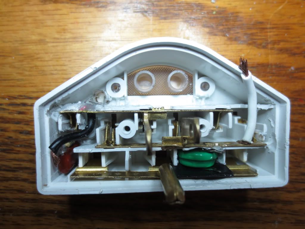
The red LED tested good with my Joule thief LED tester, but it would only flicker with 120 VAC.
I checked the thermal fuse between the MOV's and found continuity from the Line voltage to the LED resistor.
That made me replace the LED as a last resort. I also added a diode in series with it in the same direction to
eliminate reverse voltage from the 110 volts AC. That may have contributed to the LED's early demise or it was defective.
Well I paid $6 at Walmart for other 6 outlet boxes without any surge suppression so... the price went up to $7.51
Statistics: Posted by burger2227 — Mon Feb 10, 2014 11:48 pm
]]>
It actually dims too, but not very well. The light is a small bulb, not an LED. We can't have that!
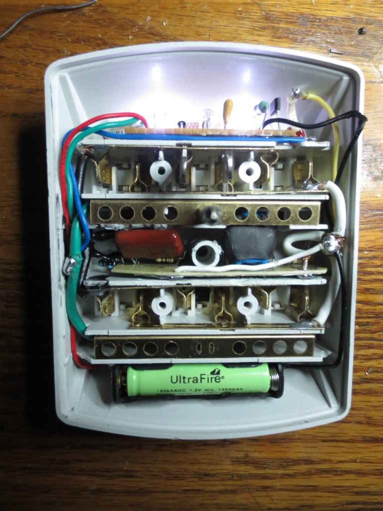
My first one I made with the 2 coil transistor circuit used a V15H battery which only lasts about 20 minutes:
A V80H should last about 4 hours. It fits nicely into the battery slot I cut out. The ground bus is taped so it doesn't short
to the plus side of the battery which is + face down. The .068 charging capacitor is on the left ready for the fuse and MOV.
This time I'm keeping the wires to ease soldering. I have also ground out channels on each side to hold the green trickle and
red battery wires. I'm using a clear LED diffusion lens holder to hold the photocell off to the left side of the window.
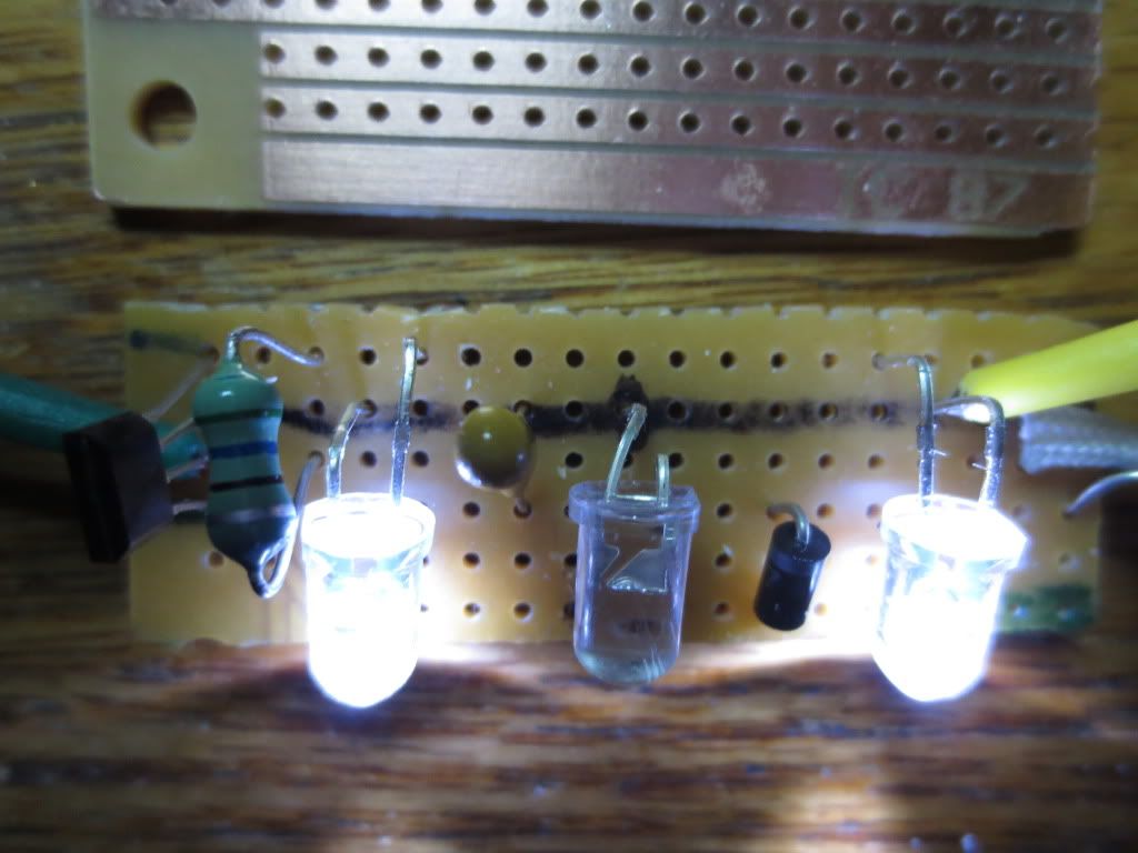
Here is the strip board with color coding for each leg of the chip except Pin 1:
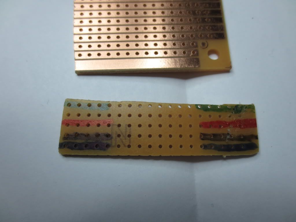
The top green row is for the trickle voltage connections of the green LED and anode of the diode to Pin 1.
The red row is for plus battery, black is negative battery and blue is for chip output to the LED anodes.
I decided to try a larger blue .1 uF capacitor that fit a bit tighter. It will give almost 2 ma charging current to the V80H battery:
There are 2 mounting openings in the window for the power failure LED's, but the charging LED is on its own.
Remember that the charging LED has the long positive anode lead going to common instead of the cathode like the other 2.
I used a copper trace board with 5 copper rows. The 5252F chip and coil are mounted on the right end.
The battery common wire had to be soldered to a black wire and then soldered to the common AC bus using the old
white wire left over from the old nite lite circuit.
The charging circuits:
The .068 uF capacitor delivers about 1.2 ma for charging and sends 1.40 volts on Pin 1 of the 5252F chip to keep it off.
The .1 uF capacitor delivers about 1.9 ma for charging and sends 1.46 volts to Pin 1 of the chip.
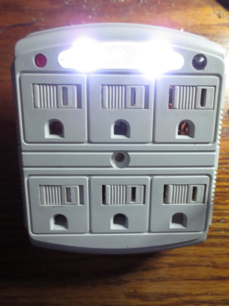
The power failure LED's may blink if the photocell gets ambient light from the LED's internally or externally.
The first time I tested the board, the photocell went into the hole wrong and the LED's blinked pretty fast.
That's why it is advisable to mount the sensor as far as possible from the light window.unless you like that effect...
Note: This particular 3 outlet box has part of the AC bus that protrudes up into the center of the circuit board area!
I isolated and sealed the circuit area with clear latex calking and allowed it to cure before installing the low voltage board.
Statistics: Posted by burger2227 — Wed Feb 05, 2014 5:28 pm
]]>
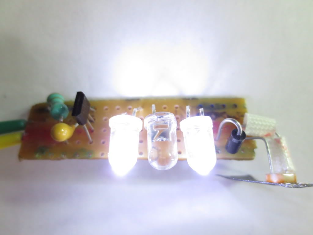
The only extra channel needed was for the small green AC wire to rectifier and green LED supplying 1 volt DC to Pin 1 on the bottom.
I never had to cut a channel, but then again, using a board of any kind is overkill. Just needed something to hold the LED's...
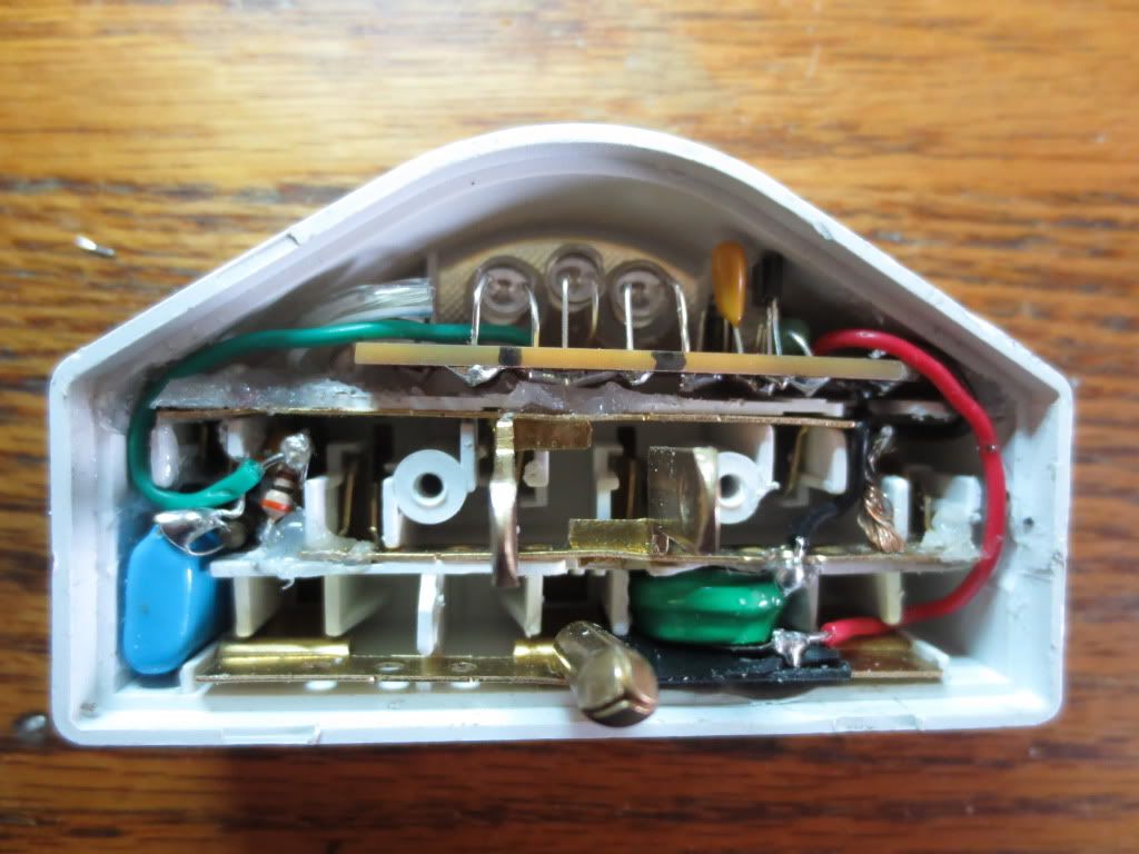
Here is the final test before I button it up for the AC test. The small green wire supplies the trickle AC to the LED driver chip:
I had to chip out a bit of plastic for the capacitor I used as it was kinda big. You can get smaller ones rated at 600 volts.
The blue wire runs from the large green ground wire to the red protection status LED so that it will not light unless there is a ground.
Stanley totally ignored the ground as I have seen other surge suppressors that at least check for a good ground. SHOCKING!
I am seriously considering using ground instead of neutral for the AC common so that no ground results in no green light.
Another thing nice about this driver chip is that the AC will run the failure lights if the battery is completely dead or disconnected.
So if all three LED's come on you know that the rechargeable battery is causing the problem.
ALWAYS use rechargeable batteries! Regular batteries cannot be charged and could burn or melt
Contact me if you are interested in purchasing some LED driver chips.
Statistics: Posted by burger2227 — Fri Jan 24, 2014 7:48 pm
]]>
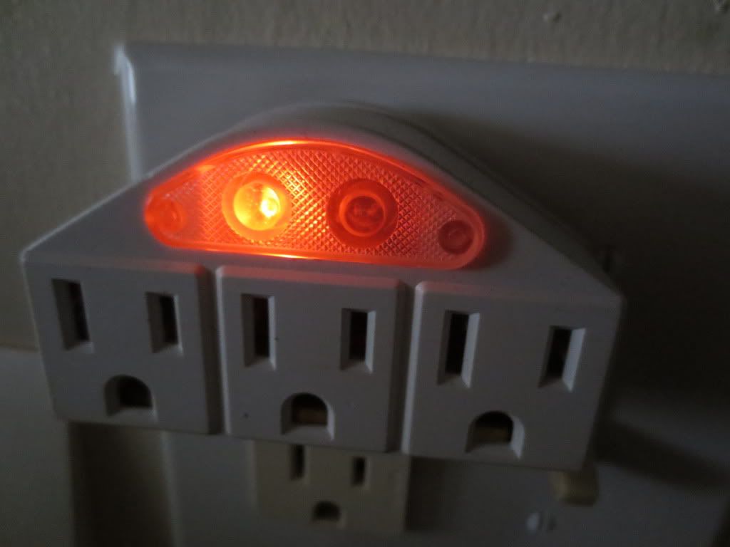
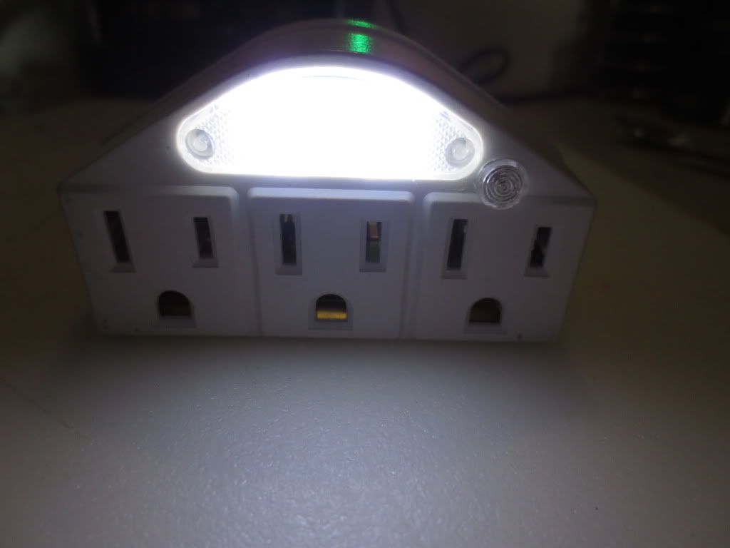
Protection is done with 3 small fused MOV's (750 J) next to a night light bulb with photocell sensor. Red LED indicates fuse is not blown.
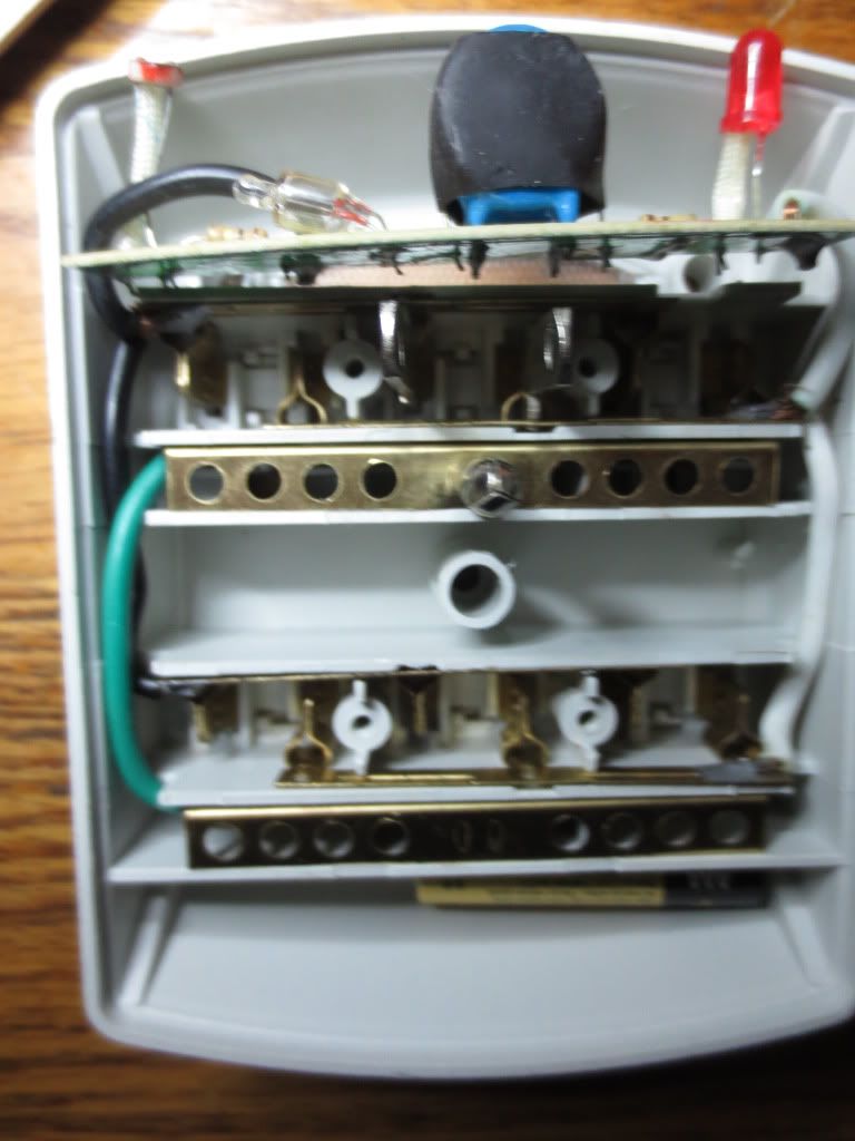
Upon closer inspection of the board, I decided it was a waste of space if I could move the MOV's somewhere else:
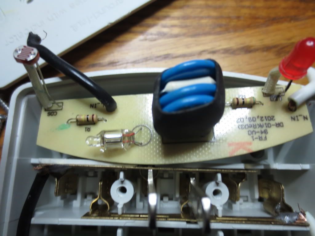
I salvaged the photocell and LED which will still be used in the MOV circuit, just not on the board.
I found a good spot for the MOV PC board under the upper ground bus. I had to grind a space out between ground holes:
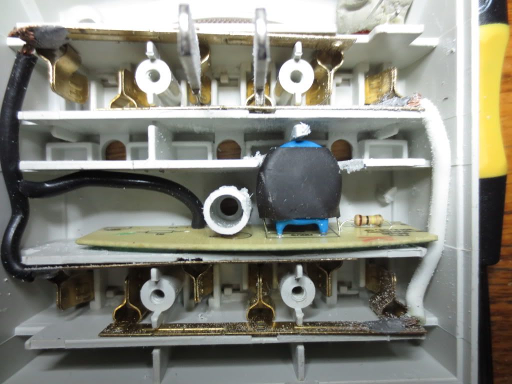
I also had to cut off the right side of the PC board a bit, but left the LED resistor and LED anode (+) wiring hole intact.
After grinding the board narrower and rewiring the common(white), I slid it in and replaced the ground bus:
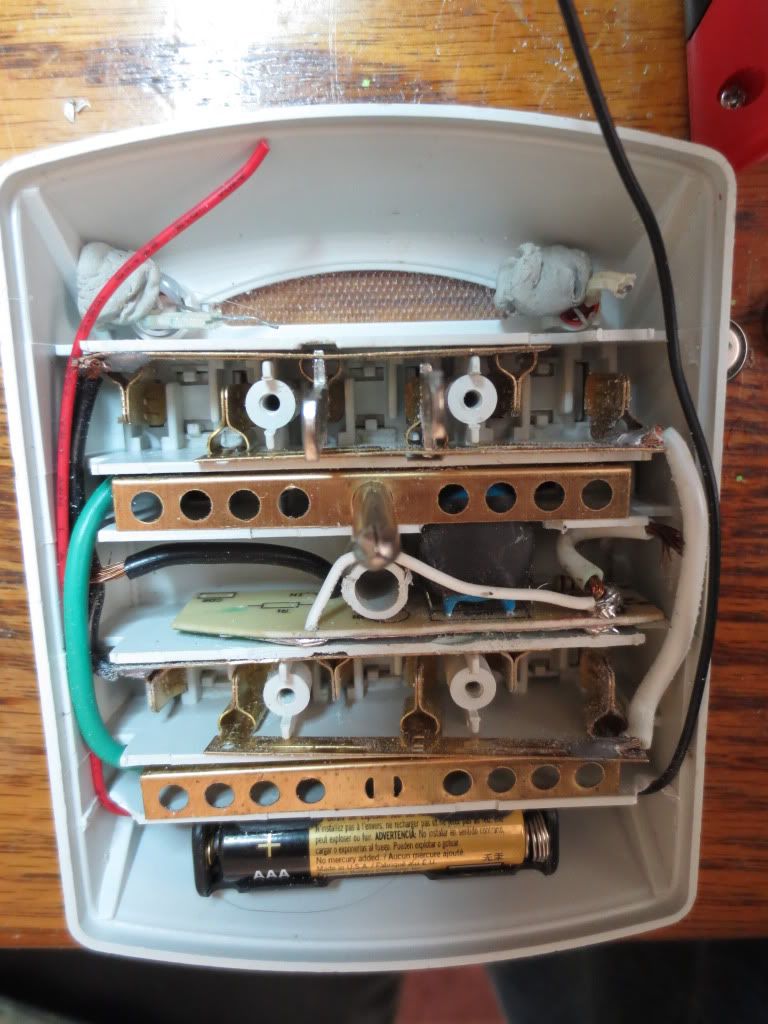
Now the top window is open, waiting for the new 5252F power failure, nite lite circuit.
Putty holds the photocell and LED in the openings so that I don't lose them...
The left side of the old PC board can be used to hold the high voltage capacitor, 30 volt MOV and resettable fuse.
Ready for the new circuit board and high voltage parts:
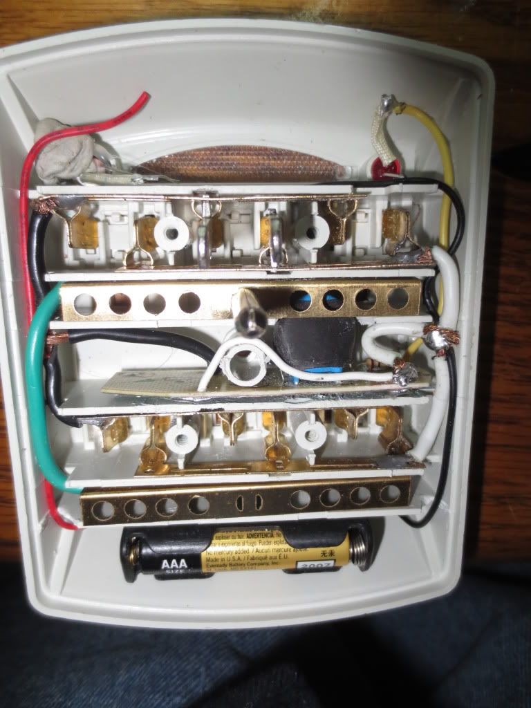
The common white is wired to the black battery wire and the yellow wire goes from the MOV board to the LED.
Statistics: Posted by burger2227 — Fri Jan 24, 2014 10:28 am
]]>
It is very sensitive to room lighting too so it saves battery power.
Statistics: Posted by burger2227 — Mon Nov 04, 2013 8:10 pm
]]>
this isolates the solar charging circuit. the can battery circuit connects the same way with a rectifier diode in series. this makes sure current only moves one way.
"the can battery never needs charging", it charges itself as the aluminum depletes. never charge it as it will deplete copper and create a toxic gas "so just use a diode in series" with anything you power.
so you have solar circuit in parallel with the can circuit in parallel with the li-on battery.
the l-ion is only a storage tank.
"now you can build a low current LED circuit to be powered with a real nuclear reactor in your home!" imagine that..
Statistics: Posted by iamdenteddisk — Sun Nov 03, 2013 6:09 pm
]]>
to make the required cell you will need (9 clean empty cans),(9*8inch strips of 10-12 gauge copper wire),(some self tapping screws).
to build
1)wiggle/break the open tab off the cans and force the lid part flat open.
2) strip 3/4 inch insulation off a strip of wire make a loop.use this loop as a screw hole and bend the wire in an "L"shape so one end attaches to a can by screw and the other end of the wire reaches through the drink hole in the can beside it. strip the end of the wire the reaches into the next can this is an electrode plate.
wrap all the cans in newspaper to insulate them from each other.
put all 9 wrapped cans in a shoe box and screw in the electrode "wire" .
once you have the battery built add 3ounces of vinegar and 7 ounces of water to each cell. your battery should make 4.5vdc. though it will drive a LED directly "kinda-dim",we won't use it for that but to charge another battery.
now I suggest a L-ion 3.7-4.2v @ 800-1000 mah rating. from old cellphones.
also to complete the project you will need 2- 4.5v solar cells I got mine from broken garden lights.
so here is the project idea and concept. a (thermo nuclear aluminum depletion reactor).
it depletes aluminum so if you plan to use it long you will want to replace the insulator material with say a plastic cup to catch the (pickle juice) for re-use.
I ran this circuit I made for the last month 12hrs a day, still super bright no noticeable depletion of either cans or copper wire but the alum is expected to deplete.
in short the solar cell do little to charge the battery so does the can battery but though we get all the sun has to harvest, it continues to charge at night from the can battery.
now I am using 3 (9can) cells in parallel at 4.5 volt. now and have all i need to use this light 12 hrs a night and still very bright after a month..
Statistics: Posted by iamdenteddisk — Sun Nov 03, 2013 5:56 pm
]]>
It lasts about 10 or 15 minutes instead of an hour so I blame it on the battery I got.
Statistics: Posted by burger2227 — Wed Oct 16, 2013 11:32 pm
]]>
the battery your using the 40mah I don't recall common cells having such low mah ratings. I think I would still use a 800 or 100 mah if possible or paralell enough to reach that. as it will require maybe a week to charge but still once it had a charge would last longer.
"emergency light"-we loose power maybe once a month with a random storm and power outages last on average about 2-4 hrs before crews get it going again but on extreme cases could take as long 4 days "normally". though a low mah rating will charge quicker 20 min of emergency light might get you to the pot for business but you'll never find the paper in the dark-right?
with emergency lights even taking a month to full charge is reasonable if you get an hour or two of light from it.. there is no real need for quick recharging "in most cases". it would be different if it was a battery backup for a heart monitor..
for the most part imo, your still on track and your project looks "commercially acceptable" or as good quality as you get from the store..kuddos!
Statistics: Posted by iamdenteddisk — Sun Oct 13, 2013 12:24 pm
]]>
]]>
Again, the 100 uf capacitor can be changed to 10 uf if space is limited and the PNP transistor will still work OK.
The battery will take a long time to become fully charged. Something like 5 days for one half hour of LED operation, but it also
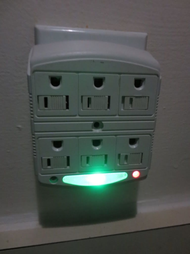
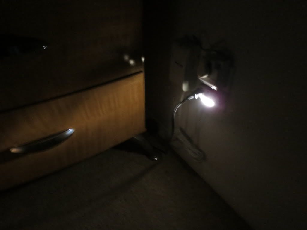
serves as a low power LED night light because I used a bright LED for the power indicator.
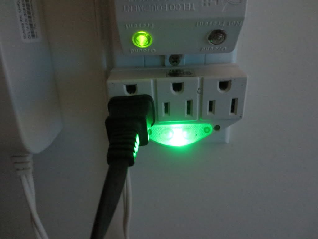
The small hole for the LDR (photocell) can be seen on the right of the LED lens as the wall outlet is wired upside down.
I really needed some extra outlets there as Verizon hogged the other one with permanent equipment I cannot move or remove.
Statistics: Posted by burger2227 — Thu Jul 11, 2013 2:52 pm
]]>