
I found some small clothes clips that I use sometimes to hold and insulate a pin while soldering so I made one into
a battery clip by trapping the positive coil lead and the ground wire wrapped around the jaw on the other side.
Statistics: Posted by burger2227 — Tue Feb 11, 2014 7:41 pm
]]>
]]>
I can get the 100uH coil, but the 4 legged chip seems to be hogged by Chinese bulk sales
merchants on line. I'm going to try to chain two and use the middle to make a center tap perhaps.
My garden lamps are still working pretty well. They stay on longer at night as the days get longer.
Here is one using transistors. I found 470uH too. Dime each,
?mH ?uH
000.470
http://www.talkingelectronics.com/proje ... Light.html
This is what I came up with using an LDR:

Big question is how much the battery will be drained during the day.
I just got the pre-made coils and other parts to try the circuit above as an LED driver for my clock.
I will post the results here.
So far the 2 LED transistor circuit has been running in the clock for 25 nights with 2 batteries...
Statistics: Posted by FrancisNash — Thu Jan 16, 2014 6:07 am
]]>
No fancy circuits here. just a switch, batteries and a flickering LED. That's what I am after!
Perhaps I can put them in a real used candle to preserve it instead of burning it up.
The ones I got use 3 LR44 button batteries, but some use one CR2032 3 volt cell.
Simply put a screwdriver in the battery cover opening and pop the guts out. No glue or screws...
The flickering LED by itself might have some interesting projects such as miniature railroad lighting or flame effects.
The battery holder could be used for other projects too though I find 3 button batteries stacked a bit cheesy.
Watch the polarity there! The spring side is positive and the red wire is actually negative!
Don't know how long the batteries will last. The miniature switch alone costs a buck at Radio Shack.
Note: The LED's will not flicker with one battery oscillator circuits. They require about 3 volts to work well at all.
Update: The larger candles with 3 AAA batteries and photocell shutoff transistor have run 3 weeks for more than 12 hours a day.
Statistics: Posted by burger2227 — Wed Dec 11, 2013 12:09 am
]]>
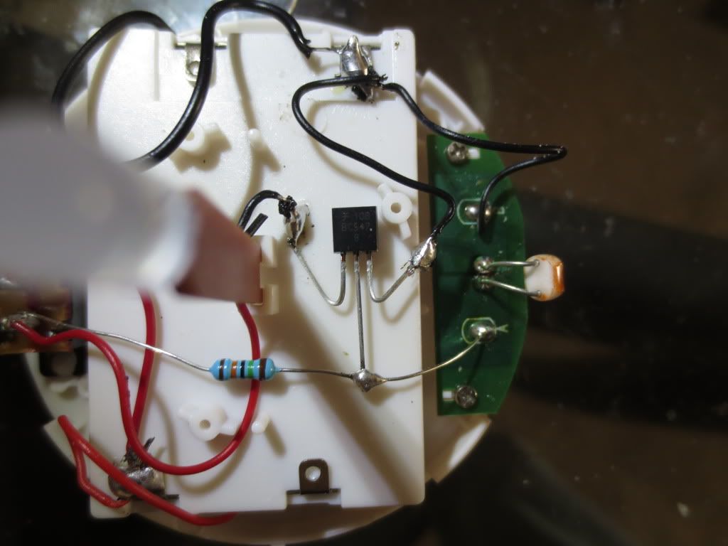
The large red wire at the bottom and black wire at top are only for testing the circuit with the CR2032 battery instead of using 3 AAA.
REMOVE ALL BATTERIES before working on the circuit board:
1) Cut the black wire from the test circuit board near the LED base and solder that end to the negative battery terminal lug.
2) Remove the red wire from the test board and solder it to one end of the 150K resistor.
3) Solder the other end of the resistor to the test circuit board where the red wire was just removed.
4) Cut the other black wire from the LED to ground about half way. Solder the LED side to the BC547 collector.
5) Solder the other half of the black wire going to battery ground to the transistor's emitter.
6) Solder the transistor base to the resistor on the test board leg.
7) Solder the photocell pins into the two test board holes left after un-soldering and removing the small male pin socket.
Aim the photocell toward the side of the candle so that the LED light above it does not affect it.
The BC547 NPN transistor is pinned the same as the schematic as collector, base, emitter left to right.
The BC547 costs 5 cents and is rated at 100 ma while a 2N2222 costs 30 cents and is rated at 800 ma.
Testing the circuit with my power supply, it works well with voltages from 2.4 to 4.5 volts with slight changes in the LED brightness.
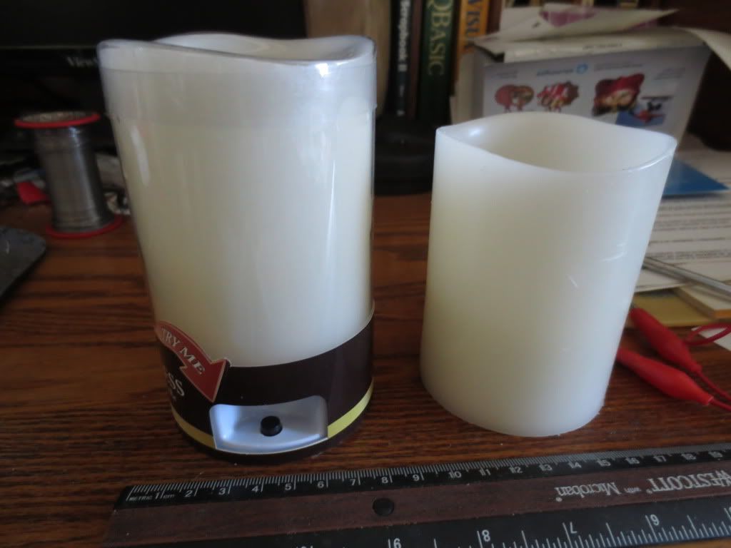
Here are the 2 candles with the LDR controlled one on the left. They both flicker with the same brightness:
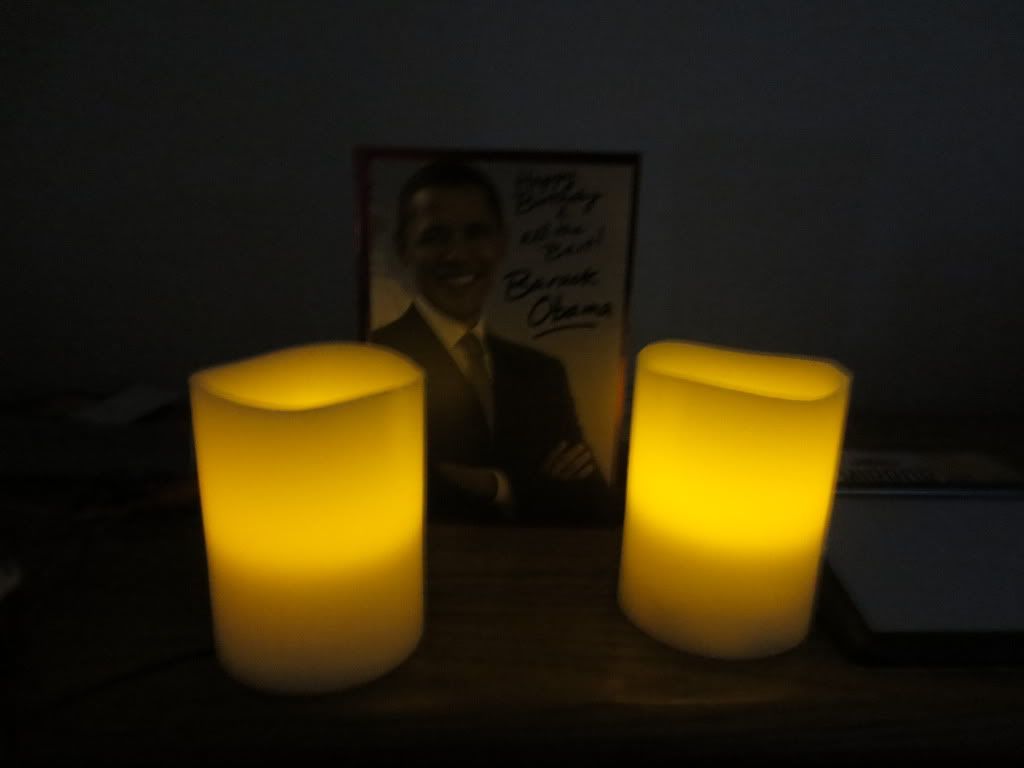
The square hole on the bottom where the test plug was tells me which way to aim the photocell, toward or away
from the room light to keep it on or off.
Statistics: Posted by burger2227 — Fri Nov 29, 2013 12:06 pm
]]>
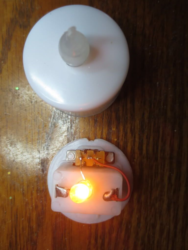
A test button circuit with battery built into the packaging allows store customers to test them:
I removed the test battery and button from the package base and jumpered the normally open pushbutton for the photos:
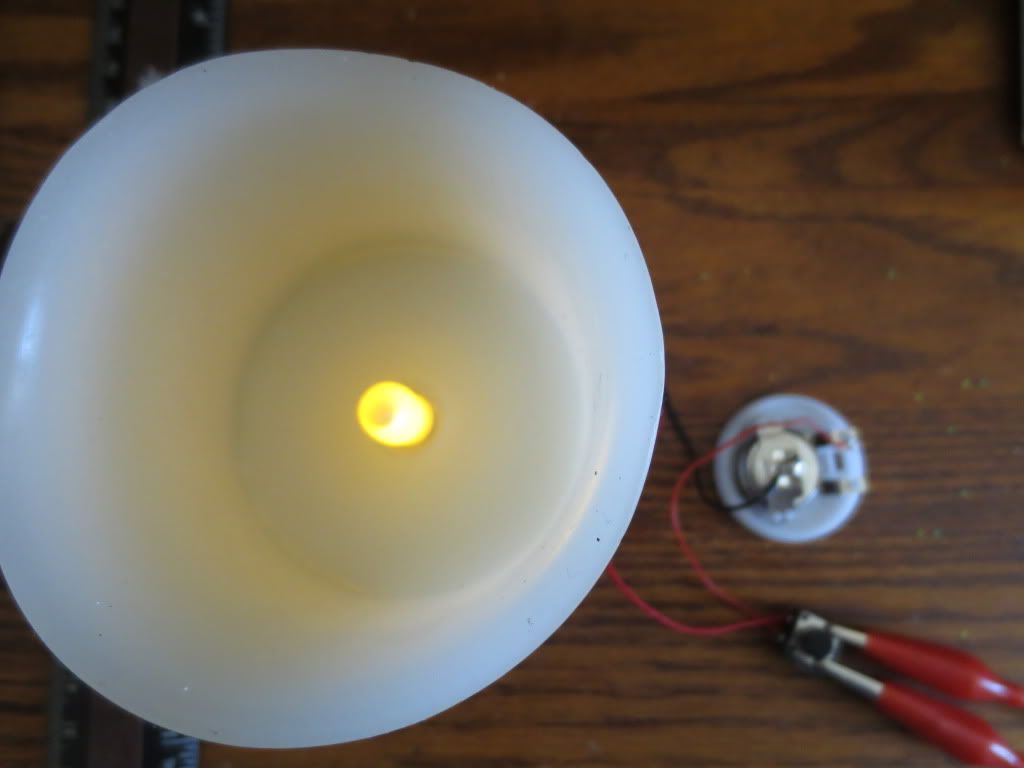
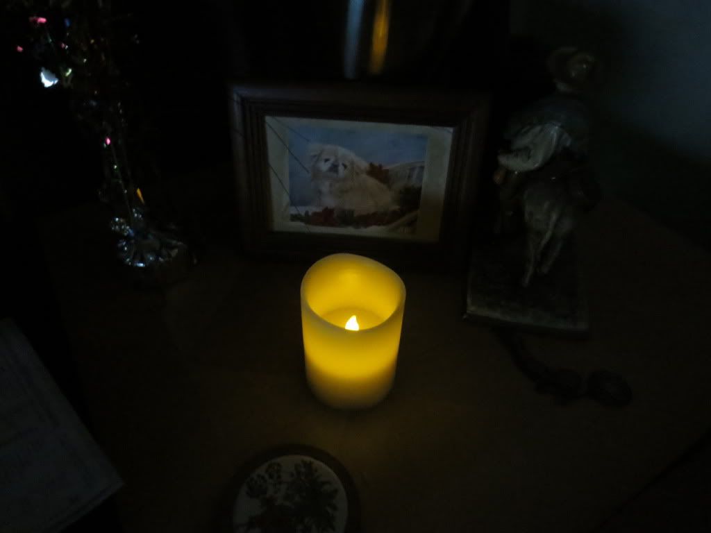
The candle center has a flame that the LED is inserted into from the bottom. It looks fake, but burned down candles don't show
it much anyhow.The candles with the white plastic wicks on top look less realistic than candles that have burned down some.
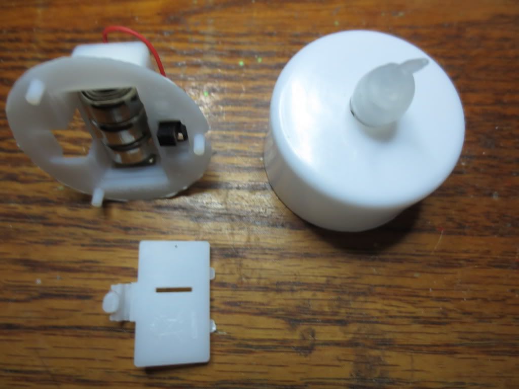
I was able to unsnap the bottom 3 AAA battery holder from the candle wax using a long flat screwdriver inside of the
battery cover flap opening on the right side. Insert the blade and push downward on the handle to lift it out of the base:
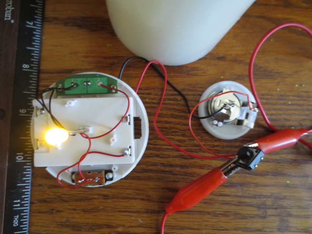
The flickering LED and resistor are on a long mica circuit board. The flickering must be done inside of the LED itself.
The flickering looks pretty realistic! The 3 AAA batteries will use the SPDT slide switch at the bottom.
Note that there are unused battery connection tabs that could be used to only use 1 or 2 AAA batteries also.
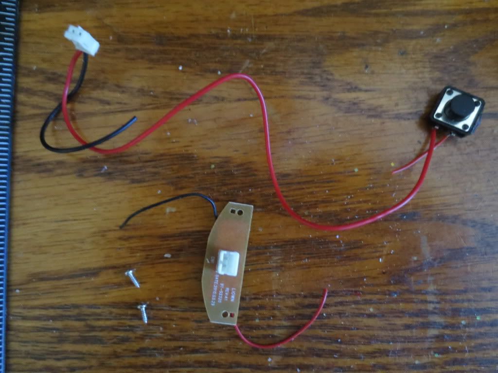
These test circuit components built into the display package can be discarded or used for other purposes later:
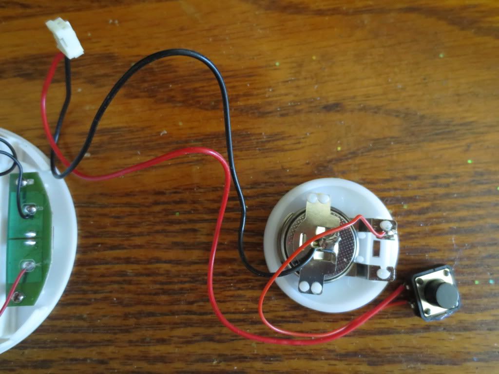
The green circuit board on the left holds the male part of the test plug wiring and is mounted with 2 small Phillips screws.
The CR2032 3 volt battery holder, the female connector wire and normally open push button can be recycled too.
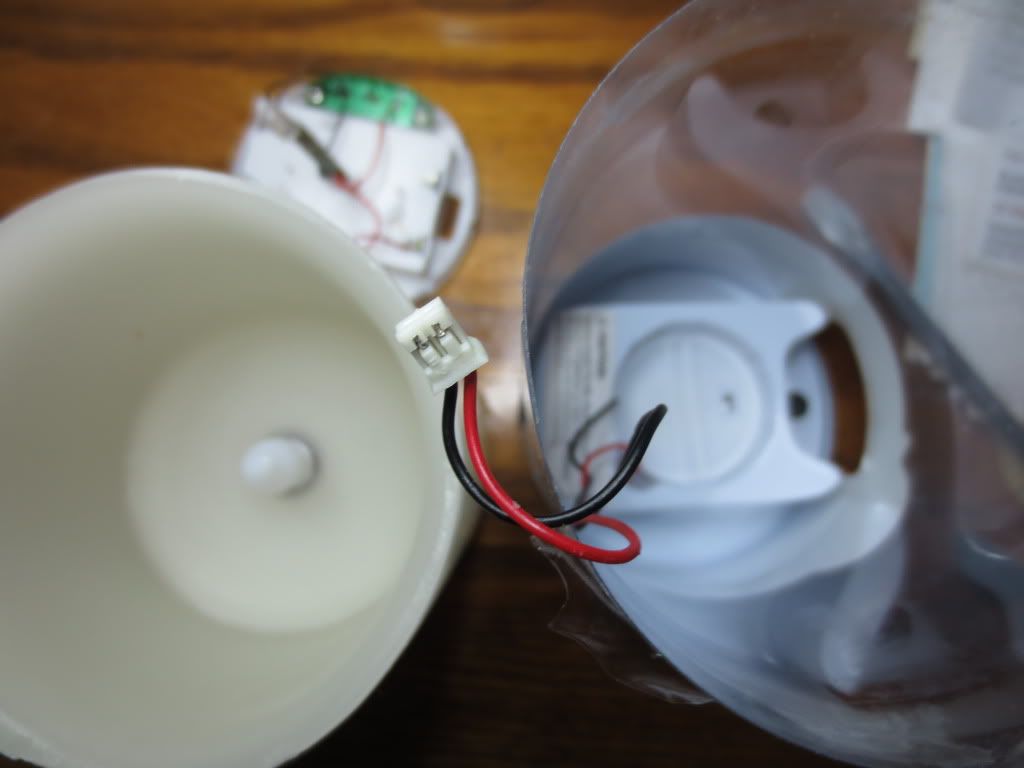
I decided to use the CR2032 battery instead of the 3 AAA batteries by wiring it through the slots for the cover plate:
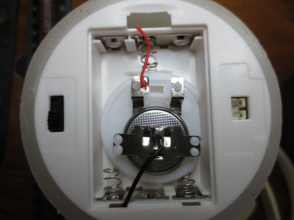
I had to cut off part of the round battery base plate and connected the red and black wires to the corresponding wires on the AAA
battery springs internally. The candle is notched near the large (top) battery cover opening when reinserting the base.
The springs help hold it in place. The battery cover can still be put on by inserting it carefully with the two wires in the slots.
Wiring the 3 volt battery to the AAA battery wires also allows it to be switched off. It can later be removed by just cutting
the wires without having to tear it apart again when switching back to AAA batteries.
Depending on how long the CR2032 battery lasts, these parts were left over for other projects:
Typical CR2032 batteries last 190 to 225 mah while AAA NiCd last from 300 to 500 ma hours.
NiMH and Alkaline AAA last 600 to 1200 ma hours. 20 of each cost about the same on Amazon.
But since we need 3 AAA batteries for every one 3 volt cell, AAA cost 3 times as much per candle.
Perhaps the AAA are brighter at 3.6 to 4.5 volts...
This is the display package base with a warning for disposal of the test battery along with battery installation instructions:
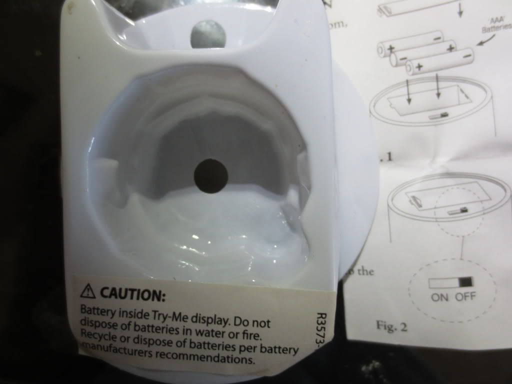
With the circular battery holder inserted upside down, it was really hard to tell that there was a battery inside of there!
The test push button must have been wired after the battery was inserted as I had to cut the display base to get it out.
The second candle's display package was harder to remove the battery and button from:
They were apparently made to stay in there! Note how fake the white flame looks when the LED is off.
This may be a good project to try a single battery LED coil circuit on. That depends on how well it will flicker.
Also I could add a photocell transistor circuit to turn the candles on at darkness like I did my clock.
The photocell should be able to see light through the candle without having to drill a mounting hole.
I could even use the test plug connector board to hold the LDR and transistor in place. There is a lot of room!
Just aim the plug hole side toward the room light...Imagine 3 volt candles turning on at night and lasting a month...
Statistics: Posted by burger2227 — Thu Nov 28, 2013 12:45 pm
]]>
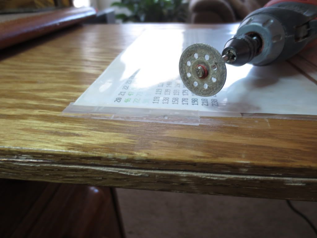
I used a Black & Decker RTX 3 speed rotary tool with an indestructible diamond wheel to cut the side slot for the wire.
Although it is not visible, the clear speaker wire for the 12 volt series LED circuit is inserted into the slot already.
I used some clear premium silicone calking to finish it off:
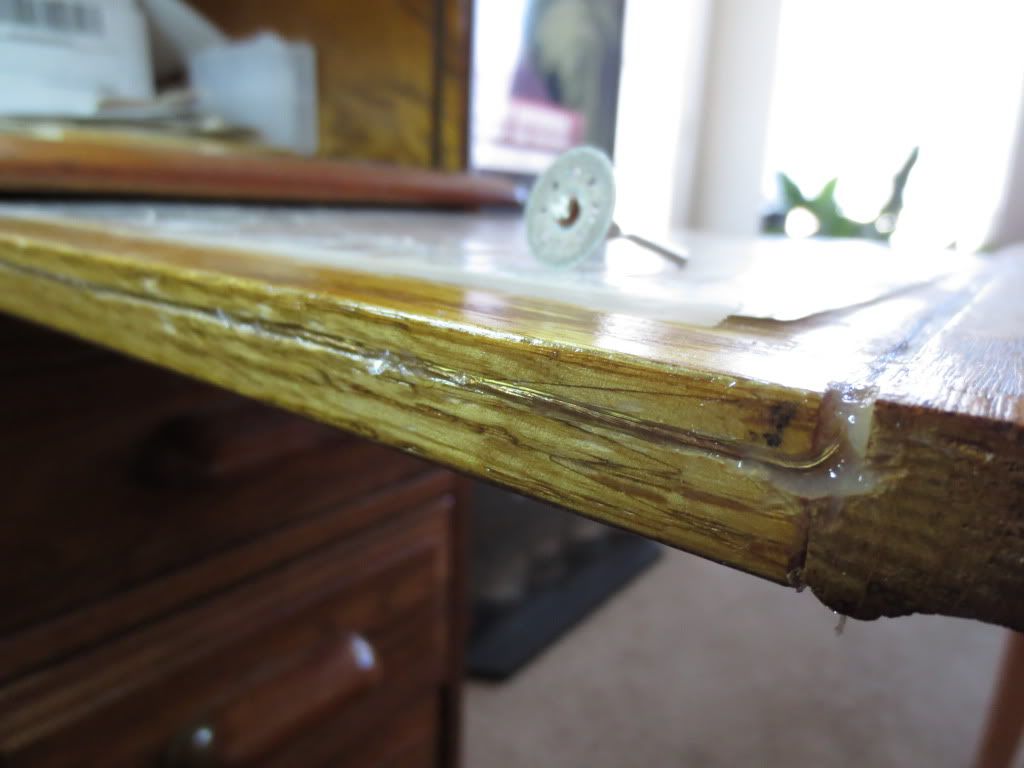
The side wire had been rubbing and made the slide harder to move in and out. Now it is easy to slide!
Statistics: Posted by burger2227 — Wed Nov 13, 2013 1:22 pm
]]>
"batteries have memory", those charged by solar cells have low "instantaneous current" memories. the old way, you had to "cycle them" which is a way of saying "give it a high current charge from time to time"(to get the oomph back).
well we know this now and use a "desulfation-charger" on leadAcid batteries but the small nicads you "shock" or reverse charge AA with 3v overrating to melt the metal slag that clogs the dialysis process in them. while the HIMH are not recoverable as I know because they are chemical batts that just dont like solar over charging. but "Li-ion" batteries have a special knack for connecting voltages or a "summing memory" remembers the best but sums overall, yet don't like summing certain ranges of applied voltage. so except in the case of 5.3 & 7.??something... the alternative is alkaline lol..
but i really like the (cap pack) things I been seeing on youtube as something I had conceived maybe 20 yrs ago but lacked resources to continually experimentally build to pioneer then.
Statistics: Posted by iamdenteddisk — Sun Nov 10, 2013 7:35 pm
]]>
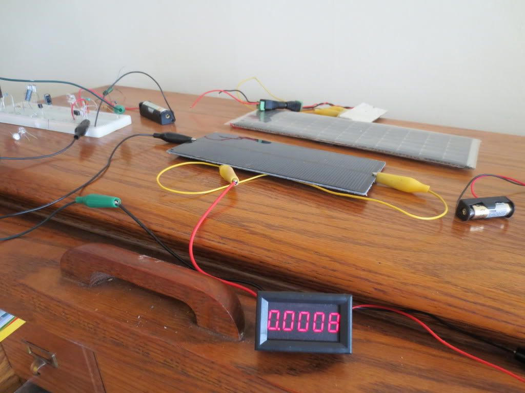
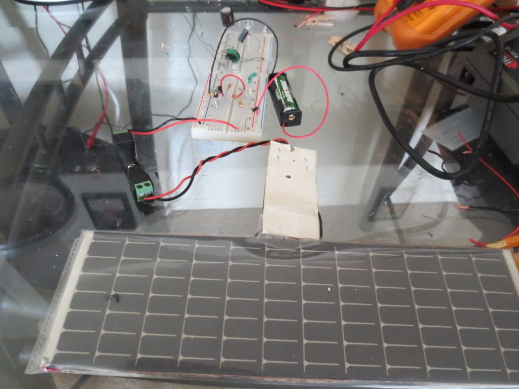
I got a small digital milliamp meter that lights up so I can see it across the room. I am using a 12 volt A23 battery
to power it and monitor current draw from the cell at the incoming diode. The new cell is smaller at 180 mm by 80 mm,
but it has more power. Still not enough to charge a battery at 800 micro amps or .8 milliamps when light levels are highest.
The larger solar cell I tried previously is not connected. Even if the cell was twice as big, the current would only
amount to 1.6 milliamps. The circuit draws 11 milliamps when the LED's are lit. The new cell even shuts the circuit
off when I turn a light on at night. So it does work pretty well as a switch.
What the one battery would need is 11 times 10 = 110 ma hours per day if the lights are on 10 hours per day.
Statistics: Posted by burger2227 — Wed May 08, 2013 8:40 am
]]>
Statistics: Posted by burger2227 — Wed Apr 24, 2013 10:39 pm
]]>
The clock batteries are on day 32 and the solar panel lights are still working on one rechargeable battery
since last Tuesday. The two solar LED's project onto the ceiling to indicate the brightness.
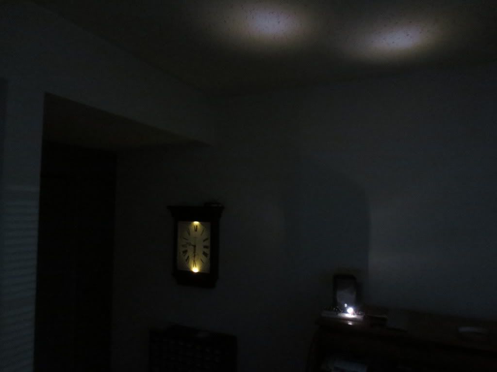
Don't look directly into bright LED's! They can harm your eyes.
The solar panel keeps the LED lights off until voltage drops to about .6 volts. On cloudy days voltage is less than 1 volt.
Today the voltage reads about .85 volts. Not enough to charge the battery which still reads 1.25 volts.
The current draw is currently 12.6 ma, so with a 2000 ma hour battery it should last 13 nights with no help
from the solar cell. That leaves another week to go, so anything over 2 weeks is all solar powered.
Statistics: Posted by burger2227 — Sun Apr 21, 2013 8:04 pm
]]>
Different photocells and light sensitivity determine the resistor value to use.
I want it to turn off when room lights are bright enough to see the clock.
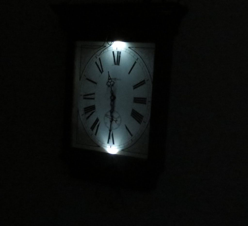
This is the clock with the new warm white 120 degree flat top LED's using the month old batteries.
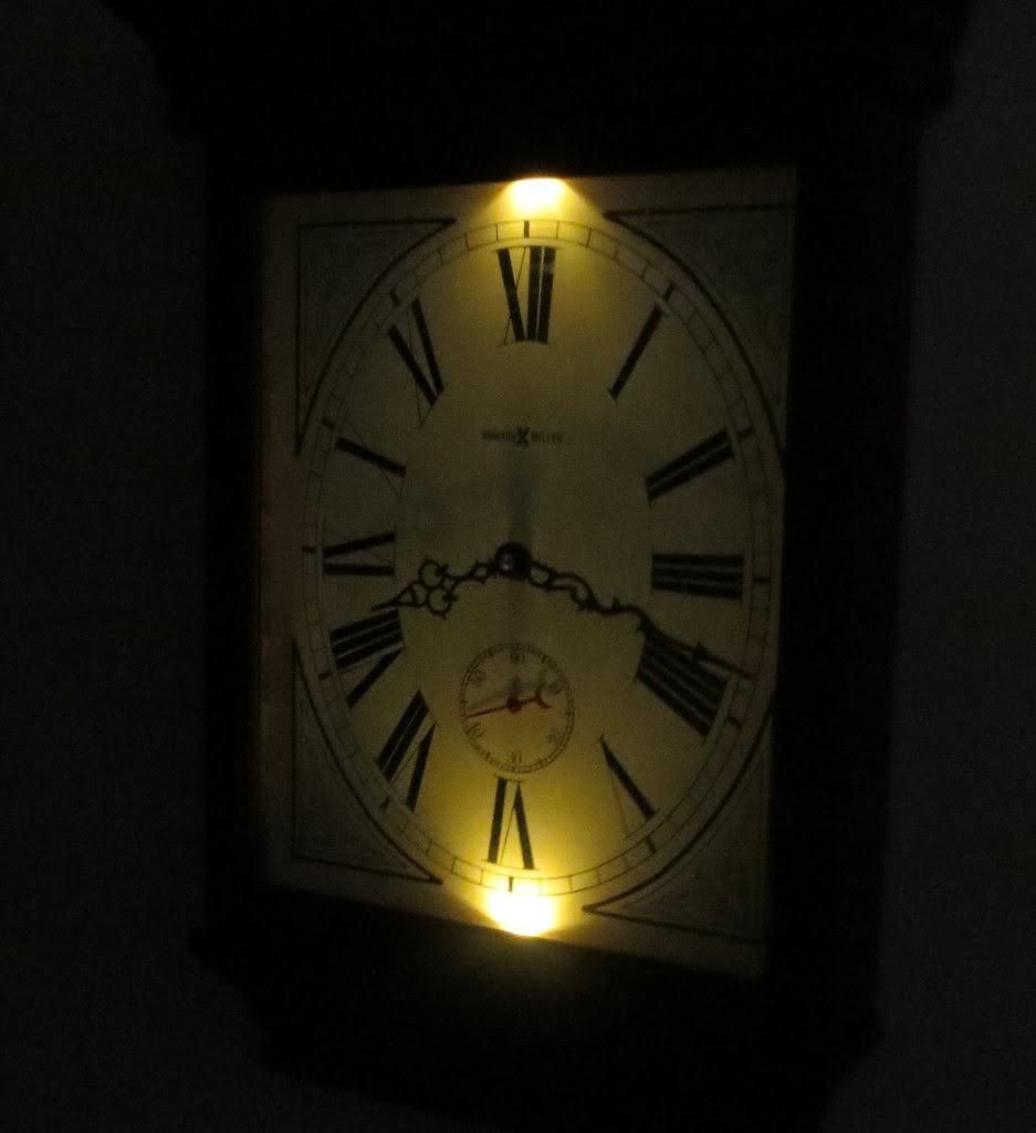
PS: The clock looks slightly brighter than the pictures...
Statistics: Posted by burger2227 — Sat Apr 20, 2013 11:19 am
]]>
The coil LED circuit controlled by the solar cell is on it's fourth night. Since the rechargeable battery is 2000 mah,
it will run at least another day. Then we shall see how well the battery is charged during the day.
Statistics: Posted by burger2227 — Fri Apr 19, 2013 10:42 pm
]]>
Current draw is not so good. My meter says about 70 ua or .07 ma. If I put a cover over it, the LED's come on. We shall see...
The solar cell is laying flat like it would if it were on top of the clock. It can be set at an angle for more current,
but I don't want it to be seen if I can use it at all.
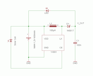
Here is the schematic again. I am not using a switch in the prototype circuit. It's all by hand...
There is another shottkey diode built into the solar cell setup so it may not be giving out the most current.
It can charge a cell phone if I put it in direct sunlight outside. Windows often block UV rays these days.
The LED's turned on at 7:20 PM. Stay on until other lights are at maximum setting. No changes in
brightness level, either on or off.
Statistics: Posted by burger2227 — Tue Apr 16, 2013 12:02 pm
]]>
coils and a .001 uf capacitor just fine. You can use the BC338 or BC547 as the oscillator.
I changed the 100K resistor to 22K for the photocell resistor. Other types may need more or less.
Current draw is slightly higher than the wire wound torroid coil circuit (27 ma) using either transistor:
BC547 uses 30 milliamps while the 338 uses 40 with similar brightness. It draws less than 1 ma when the LDR
or solar panel shuts it off. The solar panel only needs to create more than 1.5 volts to charge a 1.2 volt cell.
I will test the cutoff with the LDR tonight. The cutoff transistor base resistor value may need to be lowered
from 100K depending on the photocell used. If you don't use the LDR, then you don't need the lower cutoff
transistor either or you could use a solar panel to charge the battery and turn it off as it was originally.
Here is the full night light circuit with the LDR waiting for it to come to life:
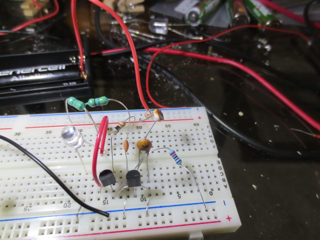
The two coils look like larger green resistors at the top with the single battery in the background.
The circuit is off waiting for it to get dark. It is using two BC547 transistors. I changed the
base resistor value from 100K to 22K to accommodate the photocell I am using.
It will have to be pretty dark before it will come on I think. We shall see!
I changed a few things such as the location of the switch and changed the diode to a Shottkey so that less
voltage is dropped across it. If the switch is turned off now, the solar cell can still charge the battery.
A Shottkey diode drops 190 mv while a 1N4004 to 1N007 can drop 570 mv or over a half of a volt.
The diode keeps the battery from turning on the cutoff transistor and draining anything through the
sleeping solar cell. The solar cell is responsible for keeping the LED circuit off and charging the battery.
I just happen to have a solar cell that can generate enough voltage that it might actually charge one cell from
ambient light in the room. It was originally bought to charge my cell phone, but I had to take it outside
for it to do anything. Maybe it can charge my clock's LED battery...
Here it is running 2 bright LED's wired in parallel. It did not come on until 7:30 PM.
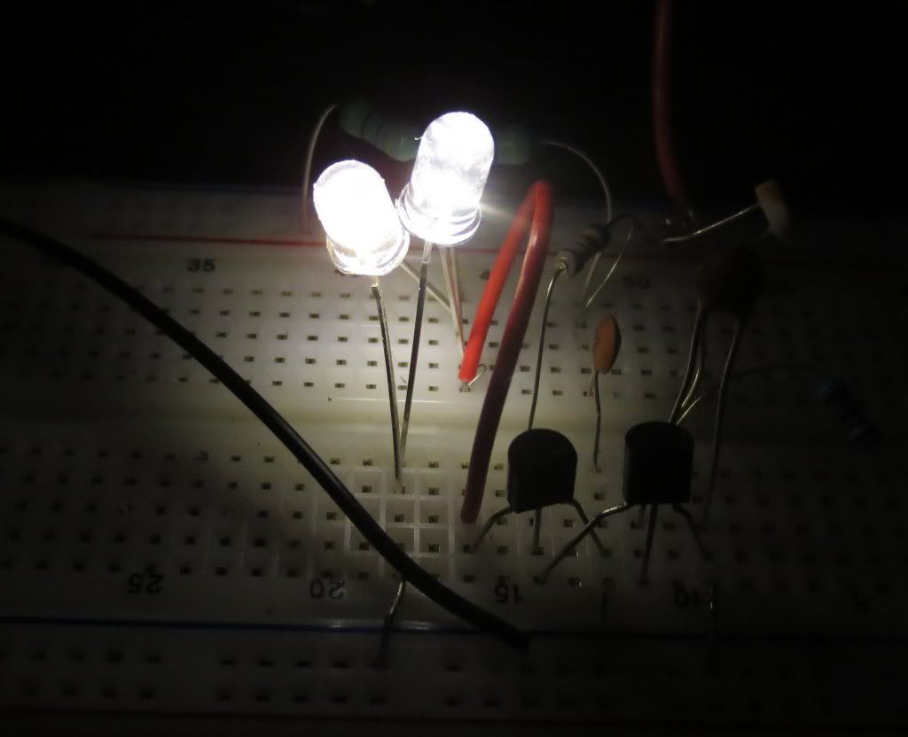
It goes out if I turn any lights on. It even gets dimmer when the TV gets brighter.
Contact me if you need a supplier for the coils and other parts. I can recommend a good parts supplier from Ebay.
To use the solar cell indoors you will need a bigger one than they have on garden lights! Mine cost $25 and still
may not work. That's a lot of batteries!
Statistics: Posted by burger2227 — Mon Apr 15, 2013 1:03 pm
]]>