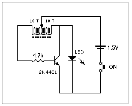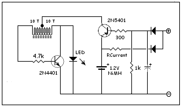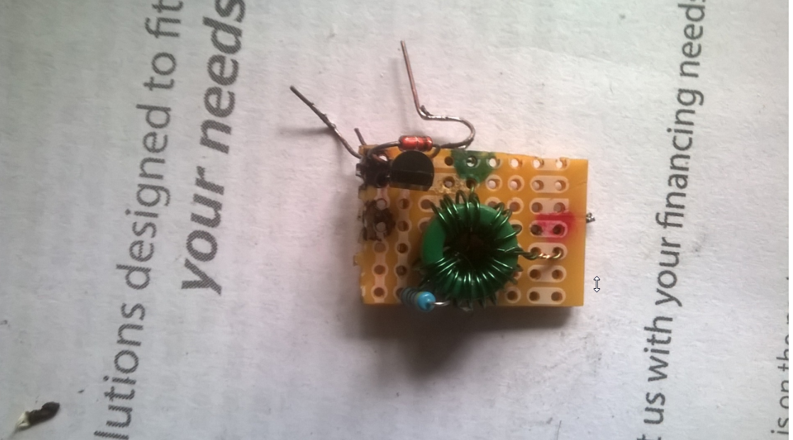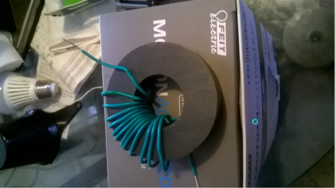
Coils can also be made without ferrite cores, but ferrite cores are more efficient and take less windings.
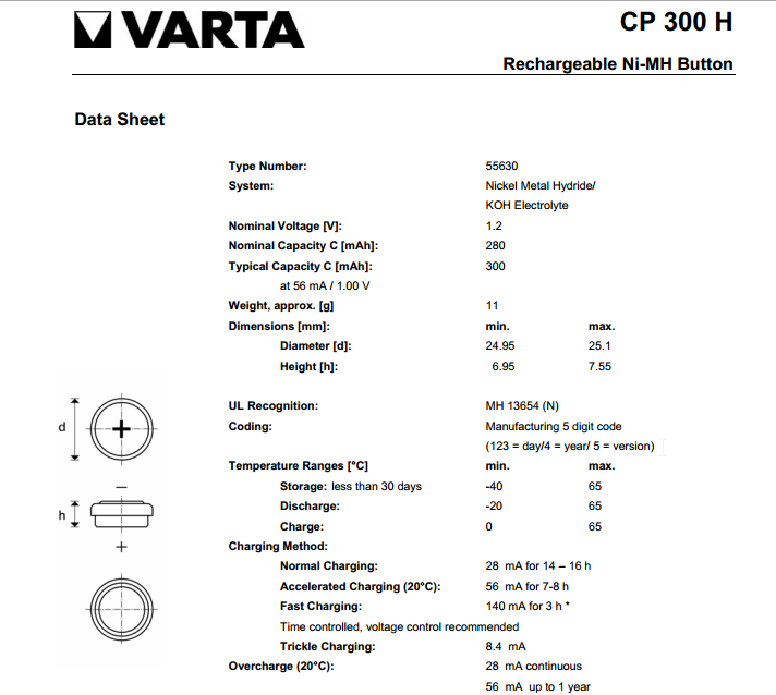
Battery voltage only goes to the center tap. The core diameter used is 10 mm and may be available on Ebay.
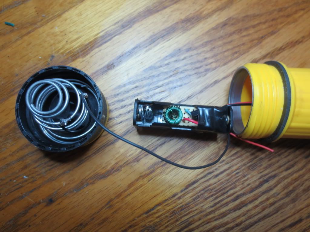
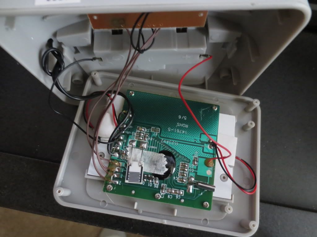
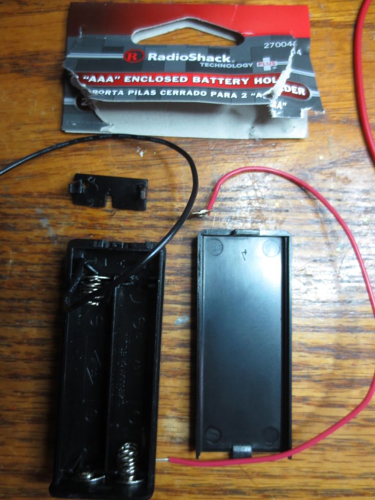
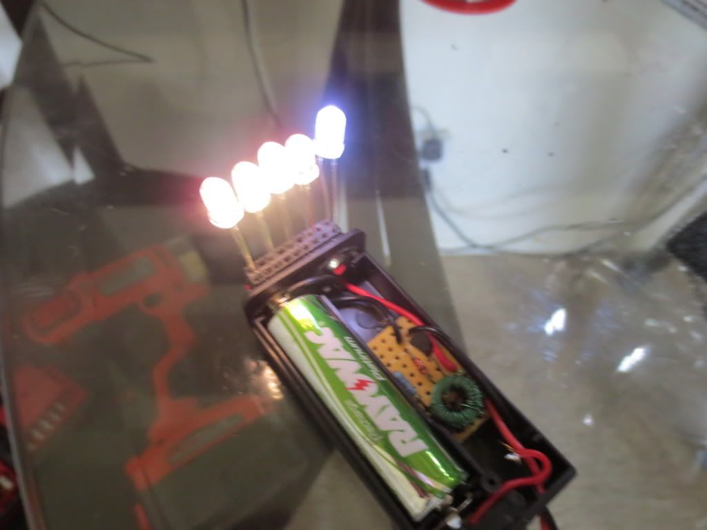
The circuit fits inside of half of a 2 AA battery holder with switch:
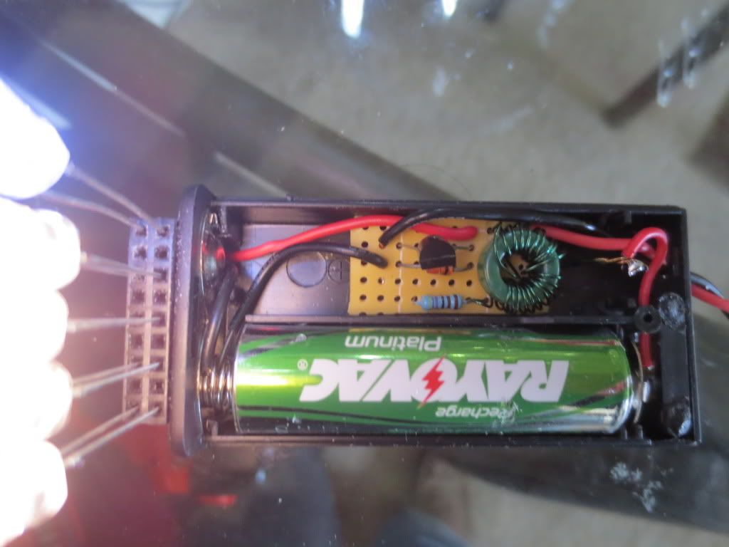
A dual pin header is used to test new LED's and compare similar brightness levels for projects.
Every LED is lit pretty brightly as this test of 5 shows. This allows the $$$ of LED brightness:
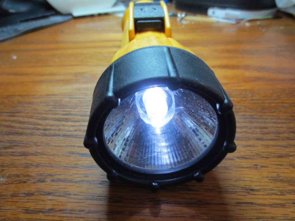
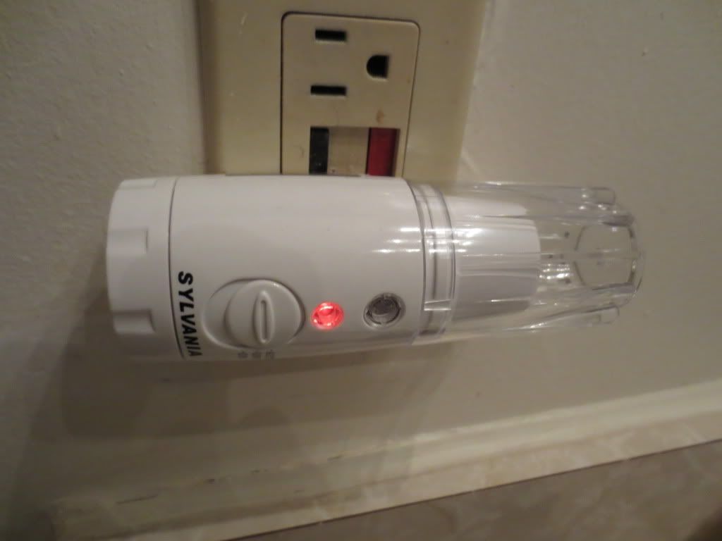
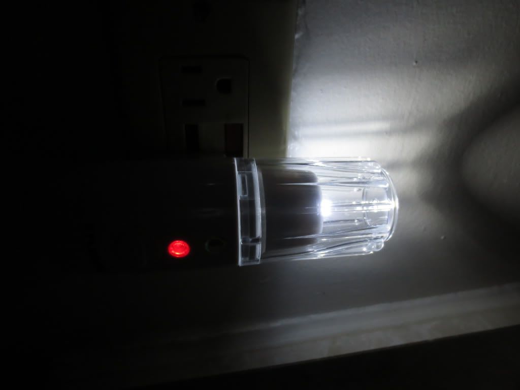
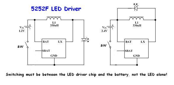
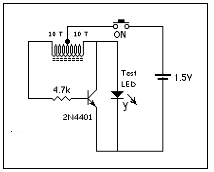
The switch sends power to the coil's center tap. This circuit could also be used for flashlights to save battery usage.
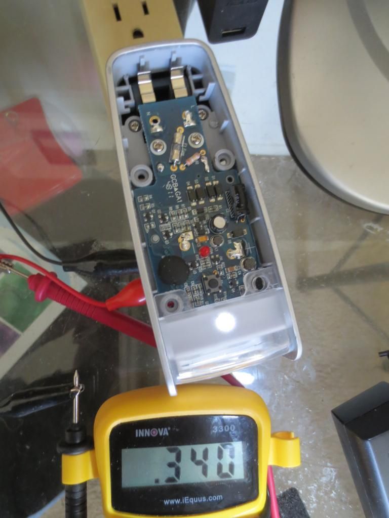
With 2 extra testing wires, it can also test external LED's in a dead circuit:
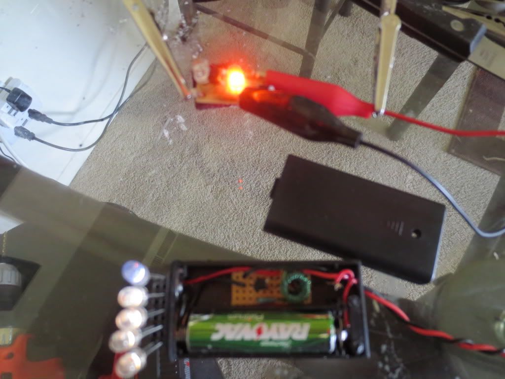
When a lower voltage LED is tested, bright ones will go dimmer as current takes the path of least resistance.
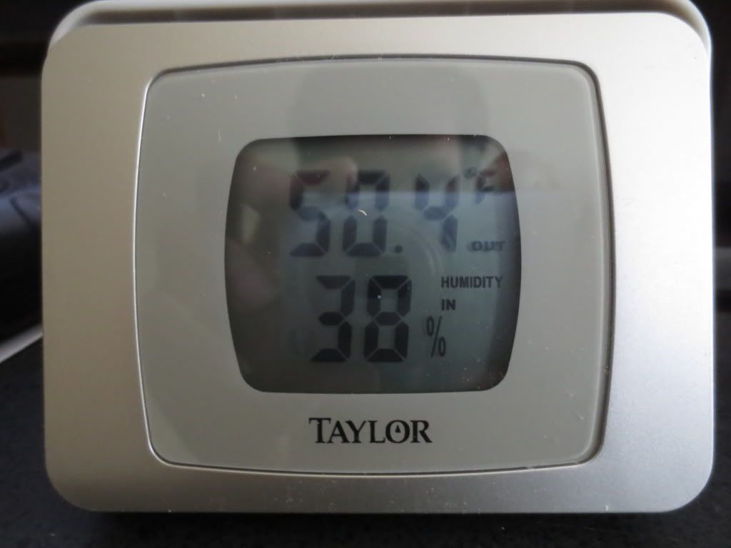
This low voltage LED pulled 15 or 20 milliamps, which is safe. Not sure which meter is correct...
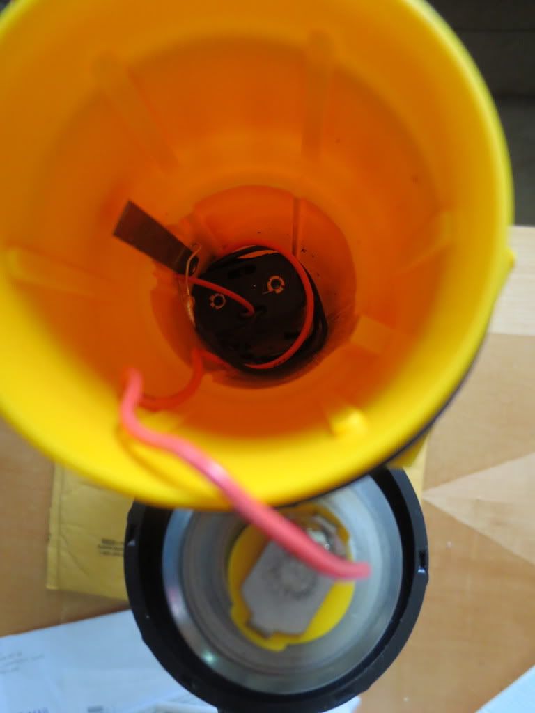
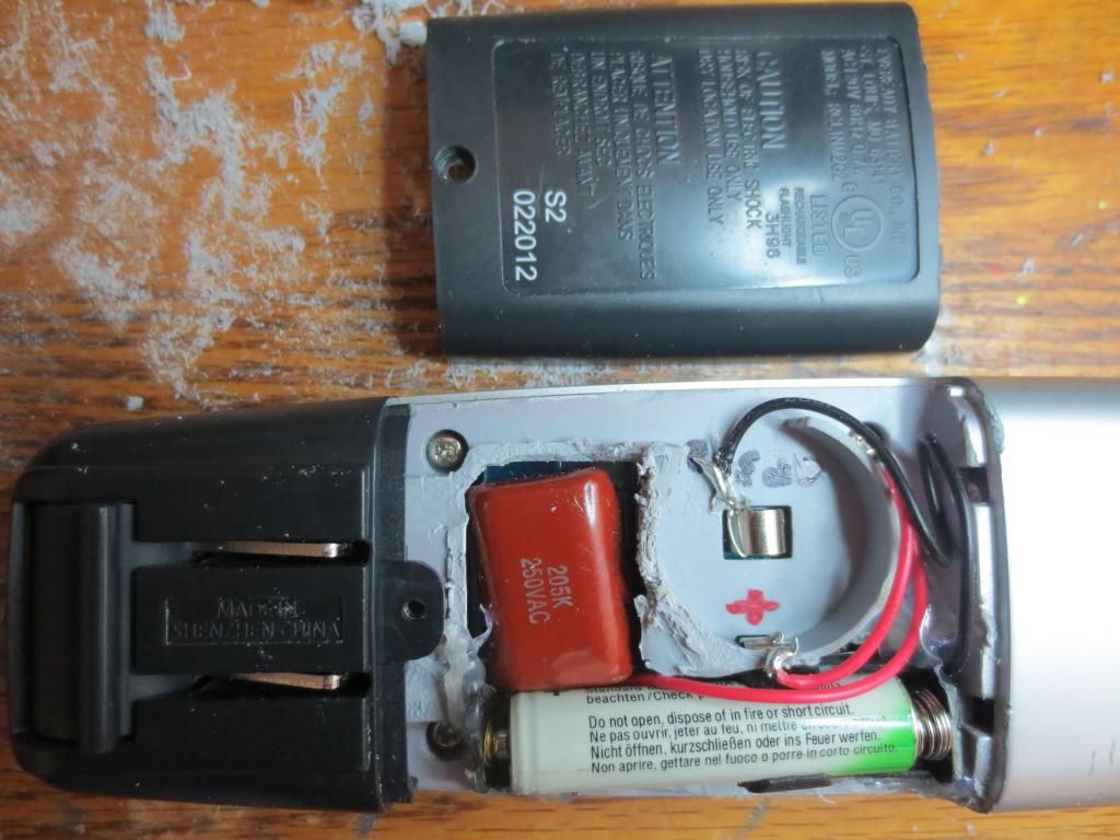
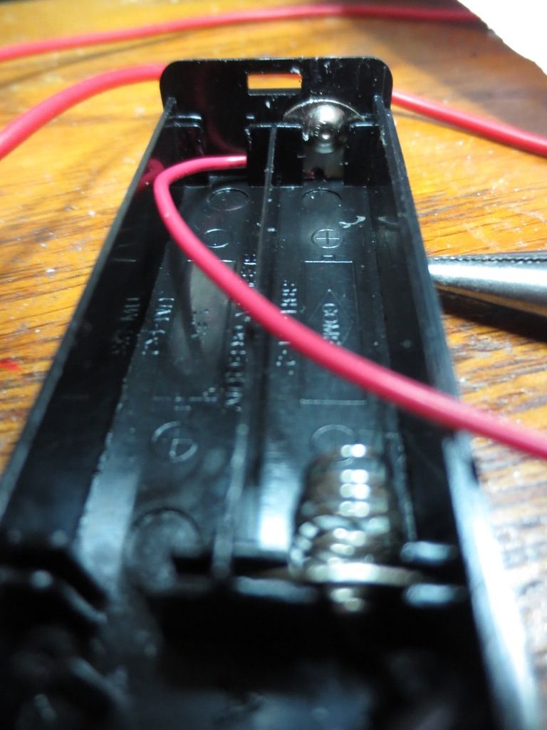
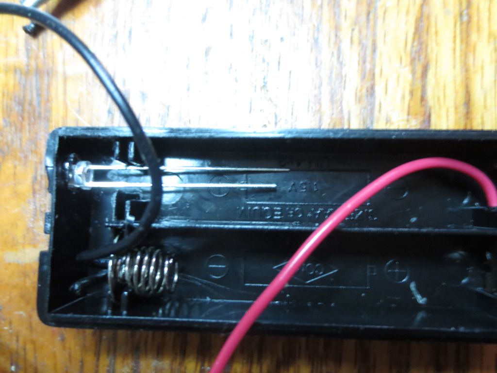
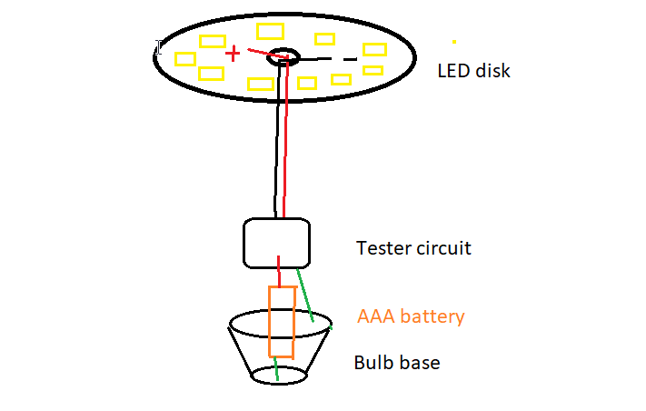
The circuit can replace the battery closest to the LED like this AAA battery box I was using 2 batteries in until today.
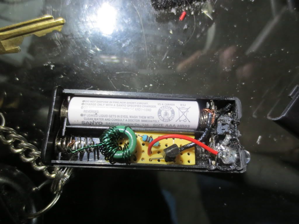
It uses a tact switch to complete the circuit to ground. The coil center tap goes to the positive end of the
rear end battery through the spring. Ground goes to the cathode leg of the LED which will be grounded by
the switch in the LED flashlight above. Running the ground from the circuit board directly to the battery
(as shown) will drain it prematurely. I found 200 microamps being drained so I changed it.
To use the circuit in a flashlight, it must have a wire from the transistor collector to the LED. It also
requires the positive voltage to the center tap and a common wire to the emitter and cathode of the LED.
Switches should isolate the battery from the circuit board, plus or minus. Most flashlights switch the common.