WARNING! Do not attempt to plug the electrical box into a wall socket
without the back of the box securely screwed back onto the box!
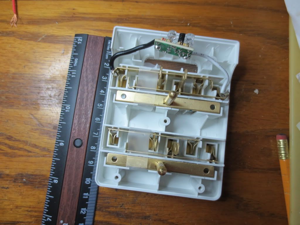
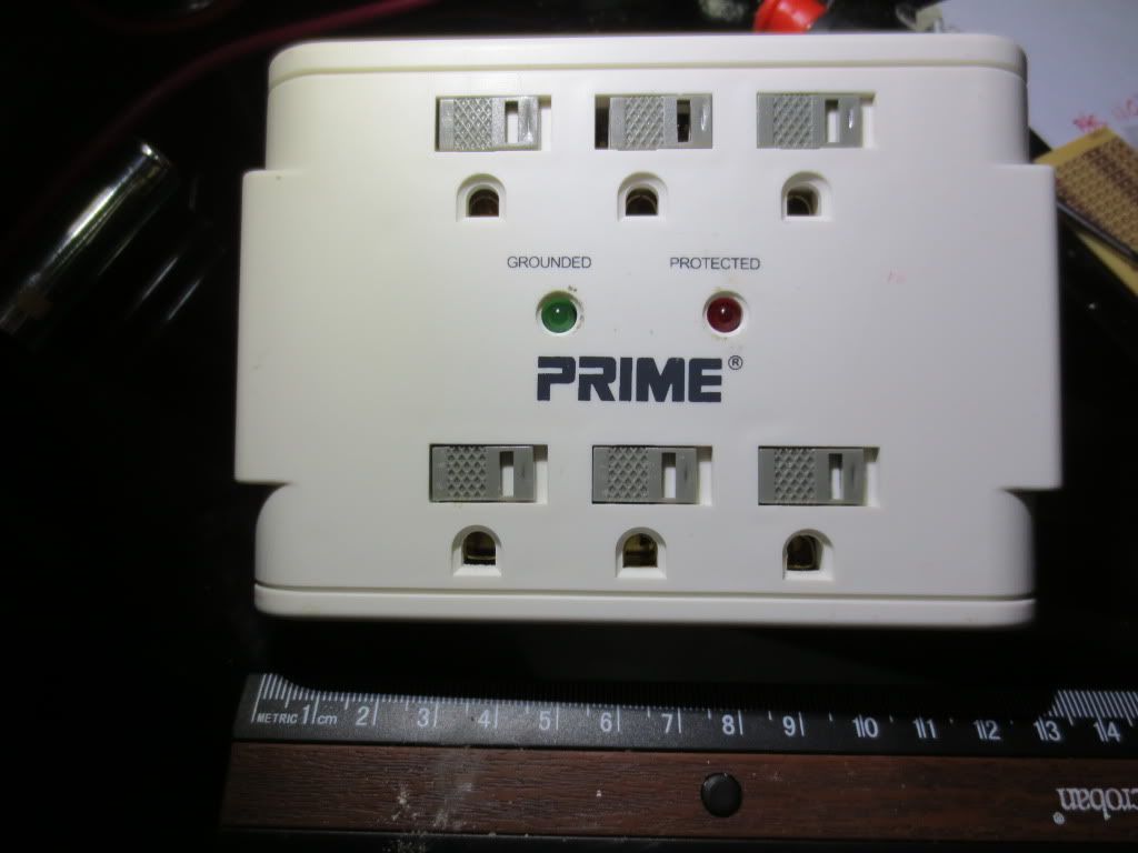
The box already had an area to put the circuit in, but it was a lot smaller than what I will need. After cutting away some
plastic and hacksawing a PC board to fit, I have this area to put the white LED circuit with the coil. I may need to stand
the coil up on its side and put it in the area on the left. Electrolytic caps could go on the right.
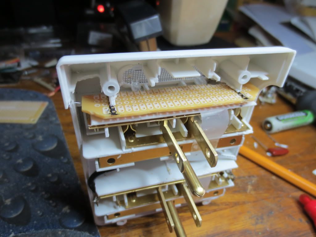
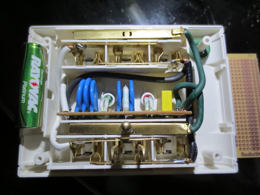
The copper clad circuit board came from Radio Shack. I had to cut the board in half to accommodate circuit requirements.
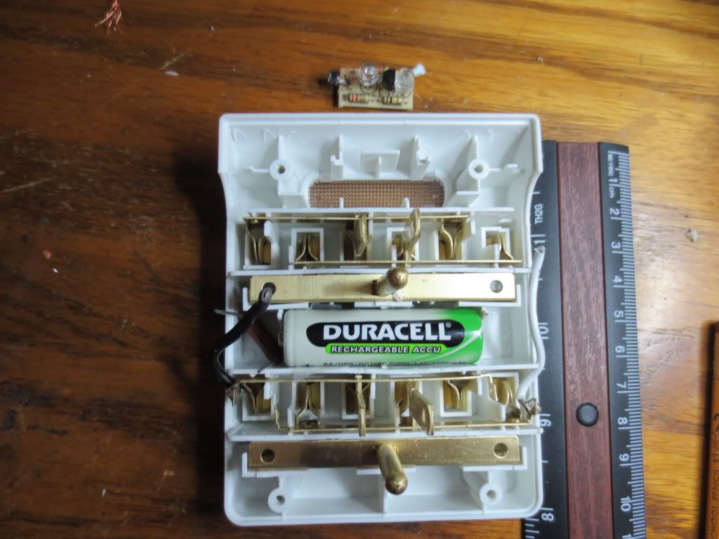
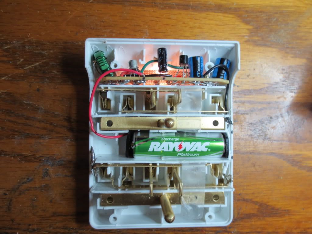
Here is the finished circuit with battery holder. I decided to use a single battery holder from Radio Shack and cut it
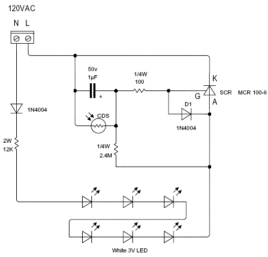
to fit. All I needed was the end contacts held together by the base. The 110 volt circuit consisting of the capacitor,
MOV, resistors and diode to the battery will go to the left of the battery.
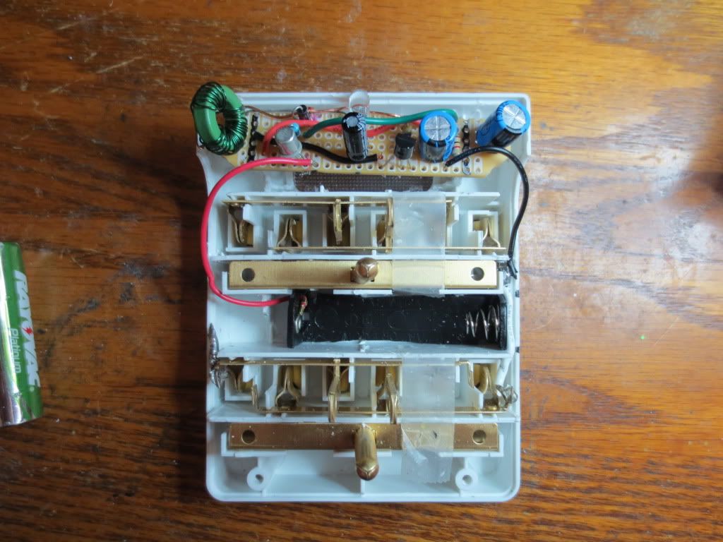
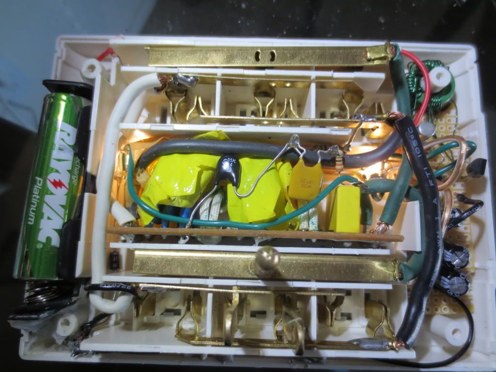
I set the circuit board up so that components requiring plus voltage or ground were placed nearest to the appropriate
wires in the box. When I first started placing components, I figured that the ferrite coil and electrolytic capacitors
would take up the most room so I placed them on the appropriate ends and worked my way into the LED placed
in the center. The space in the middle fills up faster than you think!
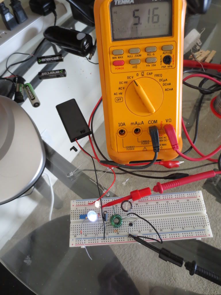
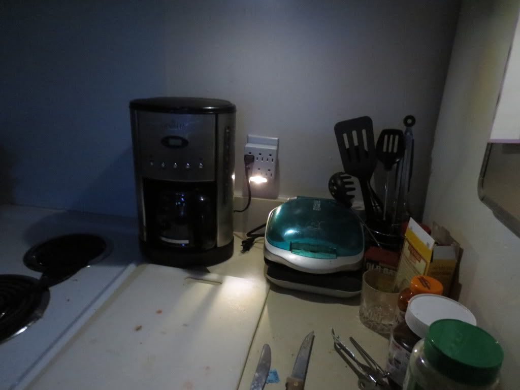
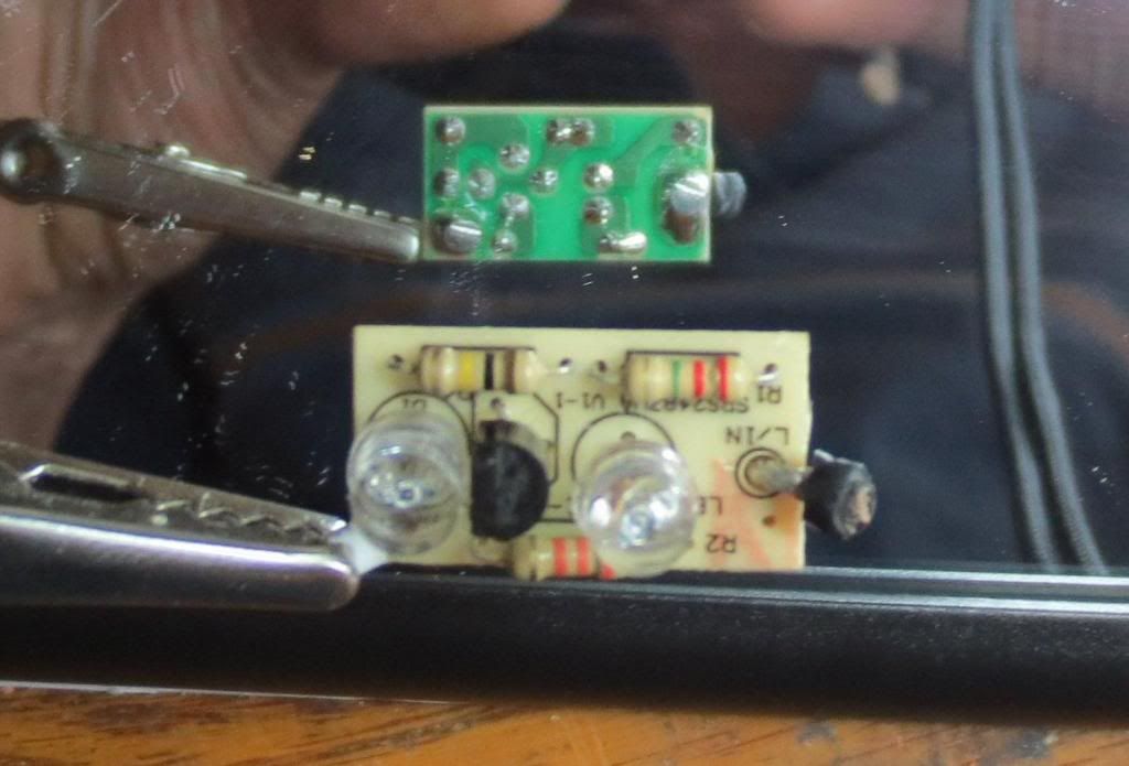
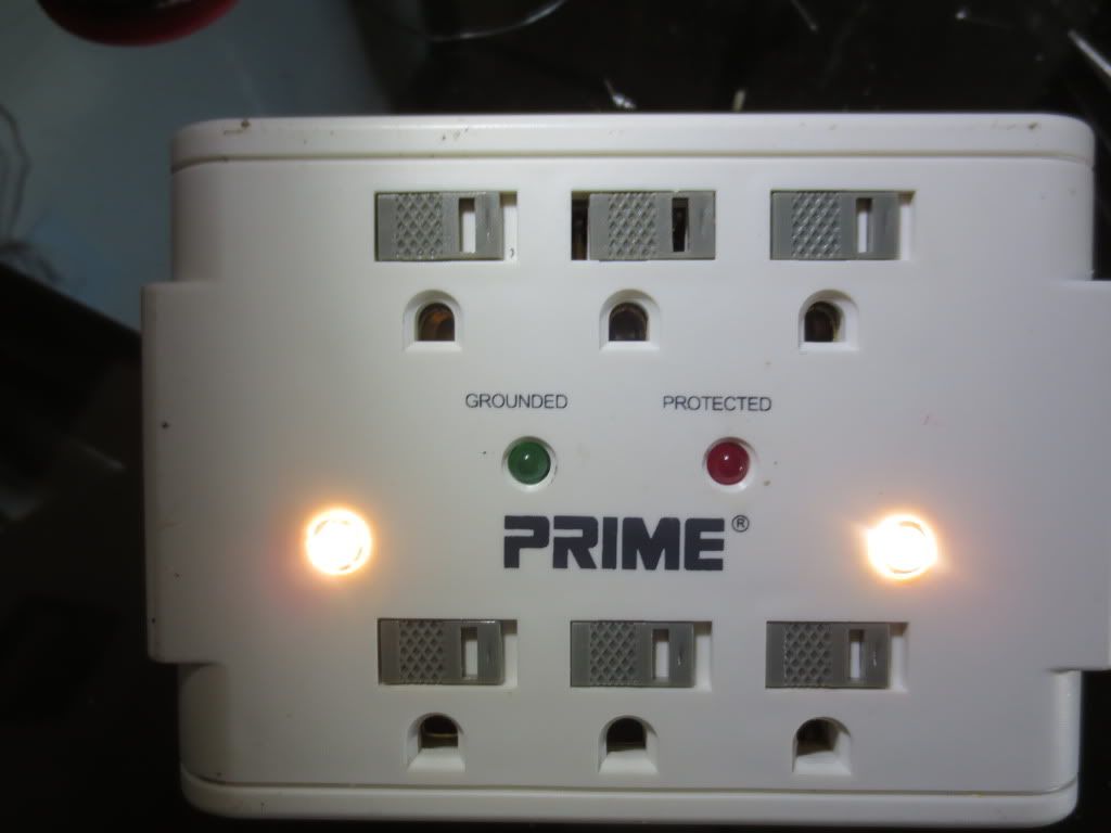
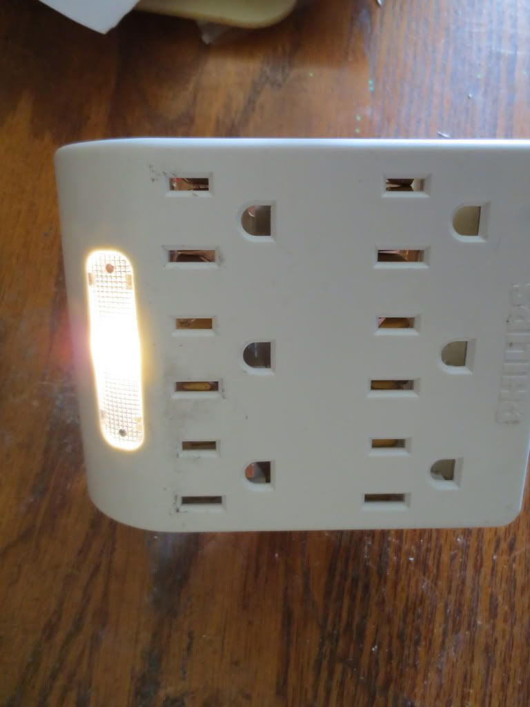
Here is the first test which went off without a hitch. I always dread the first test because I often find I have missed
something and will have to spend hours figuring what I did wrong or find a bad connection.
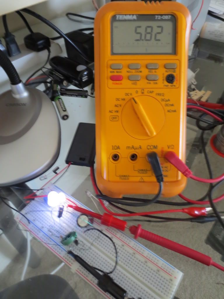
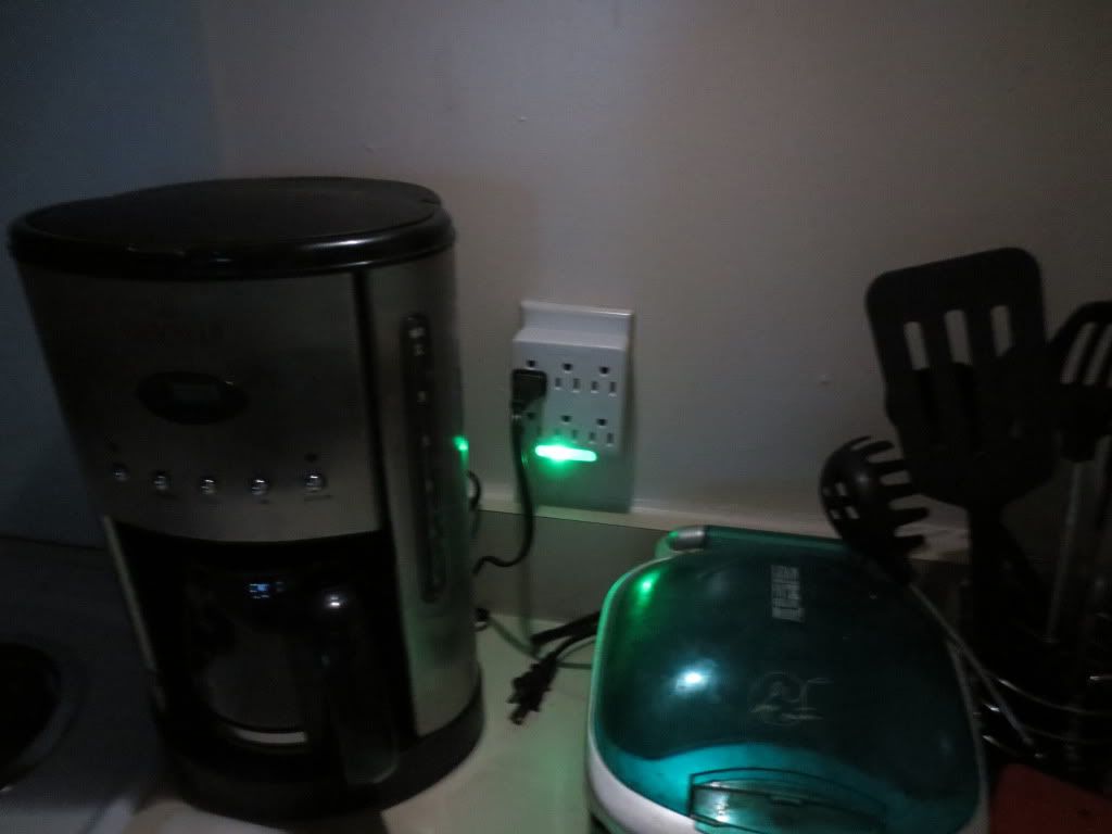
Here is what the final product will look like when the power goes out. It gives off plenty of light!
I am still waiting on safety components to complete the 110 volt part of the project. Richard Cappels, the author
of this project, was nice enough to send me some 25 volt varistors to protect the battery circuit components.
He resides in Thailand... He has also provided knowledge and assistance in making this project work as designed.
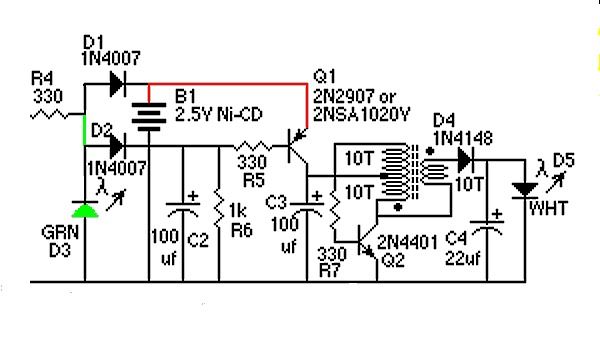
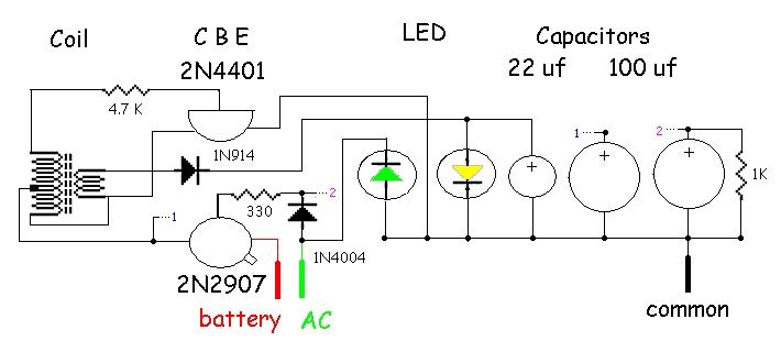
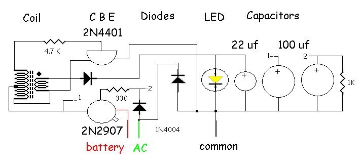
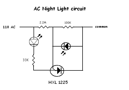
I have not added the green LED(D3) that will run off of the AC voltage yet either. There is room for it next to the
bright LED and it will require a wire from the AC capacitor circuit as will the diode to the base of the 2N2907
transistor which is already mounted on the board. I will update this as I go.
Note the orientation of D3, the green LED. The cathode (short leg) goes toward the incoming AC voltage,
but since the AC is not rectified, the LED will light when there is AC voltage using the reverse duty cycle.
It will turn off when there is no AC power and the battery driven LED circuit should come on when the
PNP transistor's base no longer has voltage on it.
Note: The AC trickle charging .068uf 300 volt(or higher) Mylar capacitor value may be designated as 683K on the case.
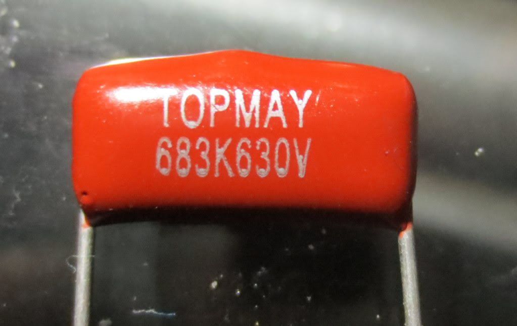 K Capacitor conversion chart: http://www.turretboards.com/capacitor_c ... _chart.htm
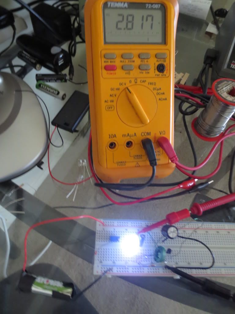
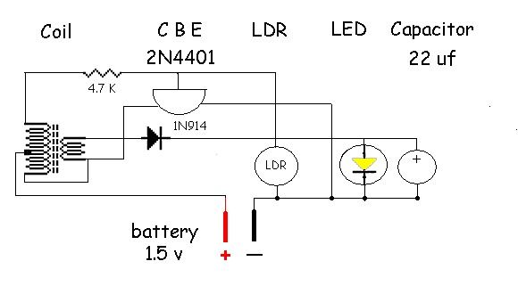
The prototype LED circuit has been running with a photocell added to the base of the 2N4401 transistor for 3 nights so far.
The LED circuit will run on the battery constantly without the high voltage trickle supply to the PNP transistor base.
WARNING! Do not attempt to plug the electrical box into a wall socket
without the back of the box securely screwed back onto the box!