Solar panel charger with auto shutoff. Solar LED drivers.
- burger2227
- Veteran
- Posts: 2466
- Joined: Mon Aug 21, 2006 12:40 am
- Location: Pittsburgh, PA
Re: Solar panel charger with auto shutoff. Solar LED drivers
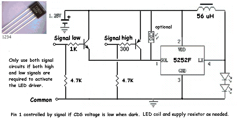
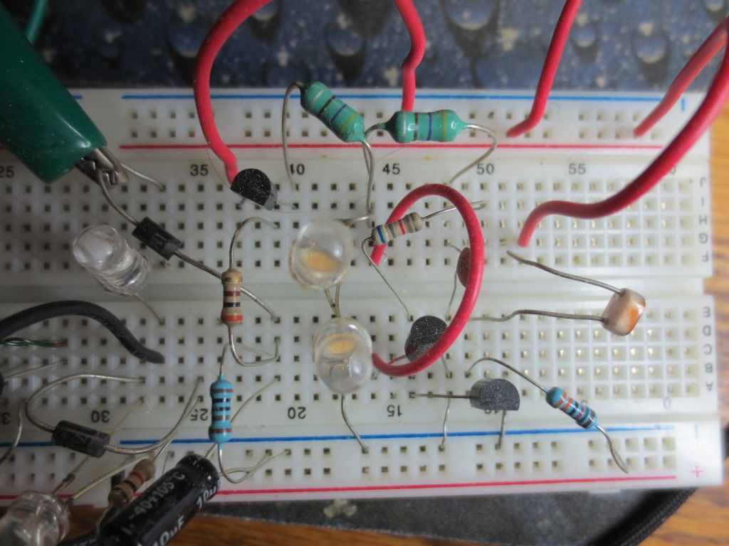
Here is what I came up with to control the 5252F chip while using a photocell to only light the LED's at night or in a dark room:
Each transistor setup conducts when the signal is not present to supply battery voltage to Pin 1 even if the CDS voltage is low.
The setup also allows higher voltage signals to be sent just by turning the transistors off.
The CDS control and Pin 1 capacitor are optional for various requirements. A 10 uF capacitor will delay the turn on time!
I tested the high signal circuit by sending @ 2.5 volts to the PNP transistor to turn it off with a PIR motion sensor module.
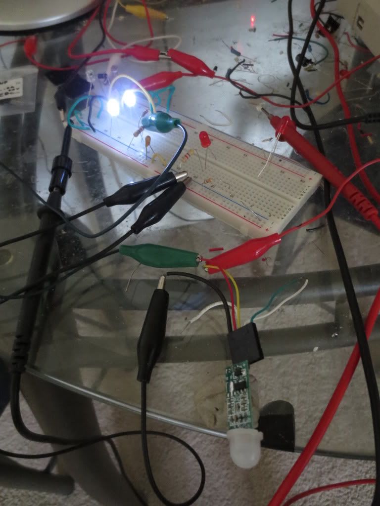
The CDS voltage becomes the only thing deciding if the LED driver should run or stay off. When it is dark,
the LED's will come on with movement, but since the photocell is facing straight up, my shadow was enough
to allow them to light up.
I kept the LED driver voltage to one battery and did not need any resistance from the battery to the transistor
with that low a voltage. I used a power supply to run the PIR sensor module because it needed 3.5 volts to work at all.
Please acknowledge and thank members who answer your questions!
QB64 is a FREE QBasic compiler for WIN, MAC(OSX) and LINUX : https://www.qb64.org/forum/index.php
Get my Q-Basics demonstrator: https://www.dropbox.com/s/fdmgp91d6h8ps ... s.zip?dl=0
QB64 is a FREE QBasic compiler for WIN, MAC(OSX) and LINUX : https://www.qb64.org/forum/index.php
Get my Q-Basics demonstrator: https://www.dropbox.com/s/fdmgp91d6h8ps ... s.zip?dl=0
Re: Solar panel charger with auto shutoff. Solar LED drivers
Hi, glad I found this thread! I've been messing with the QX5252 the last week, making a nice little minimal Joule Thief-like setup.
But I've run into one quandary, and wondered if any of you knew a way around it.
As mentioned before, the chip will turn off the light when the voltage gets below 0.9 or so, to prevent over-discharge of a rechargeable battery.
But in my specific application, I'd like it to just keep going - to NOT shut down, but instead just drain the battery to nothing. I'm not using rechargeables, but rather old "dead" AAs.
Any thoughts on how to bypass or disable this feature? I actually want it to drain an old AA down to as low as it goes, and I don't care if it gets kind of dim after a while.
----
Here's the back story about what/why I'm doing if you're curious...
I'm looking at building some small lights for recycling stations at a festival that goes on for around a week. I need about 100 of them, and it's got to be cheap, easy to make, and low maintenance.
My thought was to use a Joule Thief circuit, and use "dead" AA batteries to run it all - which would really be in the spirit of recycling and all that. I could load them up with "dead" AAs (i can get hundreds at work), then just keep an eye on them during the festival and swap out the ones that finally go out. I'm used to toroid-style Joule Thief circuits running for a week just fine, so I know this doesn't have to happen often.
The problem is, when I use "dead" AA batteries with the QX5252, I only get about a day's worth of light out of them with this chip. Specifically because the low V cutoff kicks in and turns it off. A standard (toroid coil style) Joule Thief light will just keep draining, and go for days and give me plenty of light. These only last a short time, specifically without using a solar cell, and a 330 uH inductor
I could just make the standard coil type, but since I need around 100 of them., that's a lot of toroid coils to wind. So when I found the QX5252 (and bought 100 of them), I thought I had my answer. Very easy to make with out much fuss. And dirt cheap as well.
- burger2227
- Veteran
- Posts: 2466
- Joined: Mon Aug 21, 2006 12:40 am
- Location: Pittsburgh, PA
Re: Solar panel charger with auto shutoff. Solar LED drivers
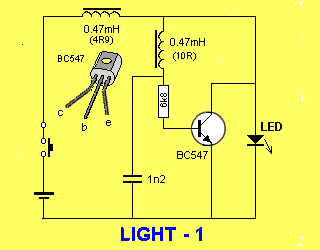
The following circuit uses 2 470 uH pre-made inductor coils:
Everything is relatively easy to get on Ebay.
Remember that those chip circuits could easily run for years with a small solar panel or other source of energy...
Everything is relatively easy to get on Ebay.
Remember that those chip circuits could easily run for years with a small solar panel or other source of energy...
Please acknowledge and thank members who answer your questions!
QB64 is a FREE QBasic compiler for WIN, MAC(OSX) and LINUX : https://www.qb64.org/forum/index.php
Get my Q-Basics demonstrator: https://www.dropbox.com/s/fdmgp91d6h8ps ... s.zip?dl=0
QB64 is a FREE QBasic compiler for WIN, MAC(OSX) and LINUX : https://www.qb64.org/forum/index.php
Get my Q-Basics demonstrator: https://www.dropbox.com/s/fdmgp91d6h8ps ... s.zip?dl=0
Re: Solar panel charger with auto shutoff. Solar LED drivers
Hey thanks for that reply and that circuit! I put it together and indeed it is a very simple and effective alternative to the toroidal coil approach. It's actually a very nice solution to my requirements of "easy to put together 100" and "works off old cast off AA batteries for a handful of days" Indeed I could add a solar panel and rechargeable batteries, but then the complexity and the cost goes up. This is just me doing something out of pocket with a strong sense of "reuse and recycle" where possible.
I really wanted to see the QX5252 work, but that low voltage cutoff is really a negative if you're looking for a simple alternative to the basic toroid-style Joule Thief that can go for a long period of time.
It's funny that you posted this circuit. I have always assumed that the two wires in the toroid had to be wound together as a pair, not as two separate coils. And literally within about an hour of your post I happened to see a picture of one which shows a toroid, but with each wind separate. It's basically the same as what the two inductor version you show does.
Thank you. You may have given me the solution of how to mass produce these (to some extent) without a lot of cost or time spent. So many projects, so little time you know
Re: Solar panel charger with auto shutoff. Solar LED drivers
PS
I'm a bit rusty on how circuits are annotated, but I'm a little confused on how both inductors are labled "0.47 mH", but are also labled "4R9" and "10R". Aren't these designations for two different inductor values as opposed to identical (0.47 mH)?
- burger2227
- Veteran
- Posts: 2466
- Joined: Mon Aug 21, 2006 12:40 am
- Location: Pittsburgh, PA
Re: Solar panel charger with auto shutoff. Solar LED drivers
Yes the coil could also be wound as a toroid coil, but I'm not sure how many loops it would take.
mH stands for MilliHenry's .47 = 470 uH, MicroHenry's. The resistance values were not a problem. Any pre-made resistor type coils will work.
The coil supplier I used was: http://www.taydaelectronics.com/" target="_blank
They also have cheap prices on transistors. Shipping is very reasonable.
Coils are also available on Ebay: http://www.ebay.com/itm/25-x-470uH-Indu ... 20da23536a" target="_blank
Here is the two coil circuit used as a power supply emergency light. Green clip is low voltage AC from a HV capacitor:
The top PNP transistor turns the circuit off. It also is turned on by a photocell when dark with the bottom NPN transistor which grounds the driver transistor base.
The circuit can run 2 bright 3 volt LED's in parallel quite easily!
mH stands for MilliHenry's .47 = 470 uH, MicroHenry's. The resistance values were not a problem. Any pre-made resistor type coils will work.
Code: Select all
mH: 000.47
uH: 000470
They also have cheap prices on transistors. Shipping is very reasonable.
Coils are also available on Ebay: http://www.ebay.com/itm/25-x-470uH-Indu ... 20da23536a" target="_blank
Here is the two coil circuit used as a power supply emergency light. Green clip is low voltage AC from a HV capacitor:
The top PNP transistor turns the circuit off. It also is turned on by a photocell when dark with the bottom NPN transistor which grounds the driver transistor base.
The circuit can run 2 bright 3 volt LED's in parallel quite easily!
Please acknowledge and thank members who answer your questions!
QB64 is a FREE QBasic compiler for WIN, MAC(OSX) and LINUX : https://www.qb64.org/forum/index.php
Get my Q-Basics demonstrator: https://www.dropbox.com/s/fdmgp91d6h8ps ... s.zip?dl=0
QB64 is a FREE QBasic compiler for WIN, MAC(OSX) and LINUX : https://www.qb64.org/forum/index.php
Get my Q-Basics demonstrator: https://www.dropbox.com/s/fdmgp91d6h8ps ... s.zip?dl=0
- burger2227
- Veteran
- Posts: 2466
- Joined: Mon Aug 21, 2006 12:40 am
- Location: Pittsburgh, PA
Re: Solar panel charger with auto shutoff. Solar LED drivers
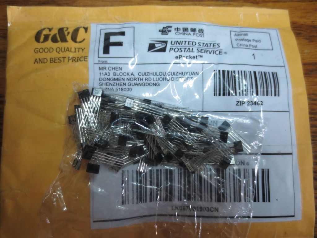
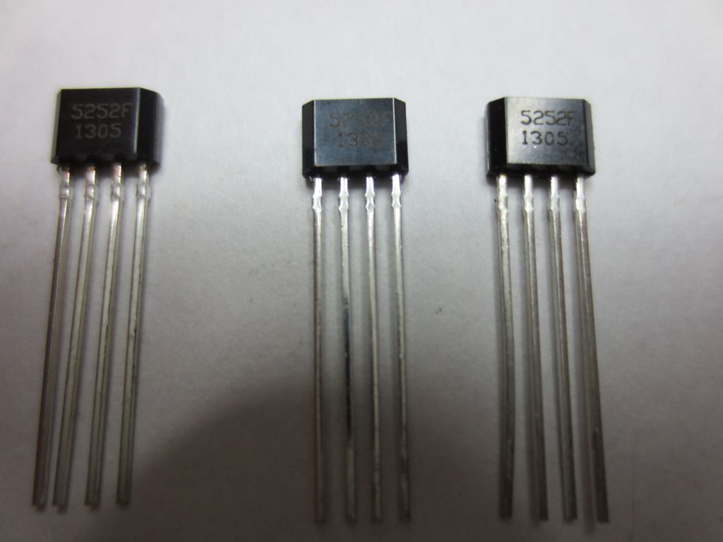
I ordered 100 solar 5252 LED driver chips from Ebay and got them within 2 weeks:
These are similar to the ones I ordered previously with a different run number:
Here is the link to order 100 pieces for $11.80 plus $2 shipping:
http://www.ebay.com/itm/100PCS-QX5252-T ... 43c410f559" target="_blank
Ebay has a ton of new sellers:
http://www.ebay.com/sch/i.html?_from=R4 ... r&_sacat=0
Please acknowledge and thank members who answer your questions!
QB64 is a FREE QBasic compiler for WIN, MAC(OSX) and LINUX : https://www.qb64.org/forum/index.php
Get my Q-Basics demonstrator: https://www.dropbox.com/s/fdmgp91d6h8ps ... s.zip?dl=0
QB64 is a FREE QBasic compiler for WIN, MAC(OSX) and LINUX : https://www.qb64.org/forum/index.php
Get my Q-Basics demonstrator: https://www.dropbox.com/s/fdmgp91d6h8ps ... s.zip?dl=0
- burger2227
- Veteran
- Posts: 2466
- Joined: Mon Aug 21, 2006 12:40 am
- Location: Pittsburgh, PA
Re: Solar panel charger with auto shutoff. Solar LED drivers
Forgot to mention that the 5252 chips can use more than one battery in series if you wire the 3 volt bright
LED's in series. Two batteries will create 6 volts so use at least 2 LED's in series. A 33 uH coil can run 2 pairs
of parallel LED's in series(4 total) at 16 ma each for bright LED's.
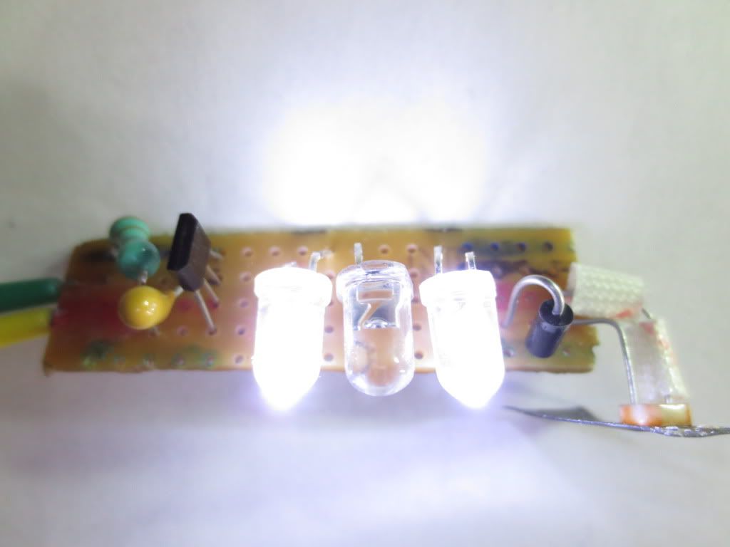
This 2 LED circuit uses a 33 uH coil and the LED's tend to blink when one AAA battery is low draining 30 milliamps:
2 AAA batteries could easily run 4 LED's with 2 more in series and probably be brighter without flashing as quickly.
AAA batteries and smaller batteries prefer less than 15 ma current draw or blinking may occur. Use AA to avoid that!
Please acknowledge and thank members who answer your questions!
QB64 is a FREE QBasic compiler for WIN, MAC(OSX) and LINUX : https://www.qb64.org/forum/index.php
Get my Q-Basics demonstrator: https://www.dropbox.com/s/fdmgp91d6h8ps ... s.zip?dl=0
QB64 is a FREE QBasic compiler for WIN, MAC(OSX) and LINUX : https://www.qb64.org/forum/index.php
Get my Q-Basics demonstrator: https://www.dropbox.com/s/fdmgp91d6h8ps ... s.zip?dl=0
- burger2227
- Veteran
- Posts: 2466
- Joined: Mon Aug 21, 2006 12:40 am
- Location: Pittsburgh, PA
Re: Solar panel charger with auto shutoff. Solar LED drivers
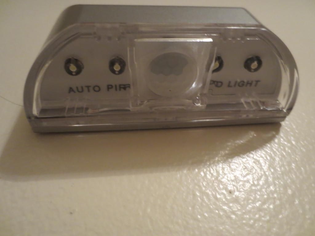
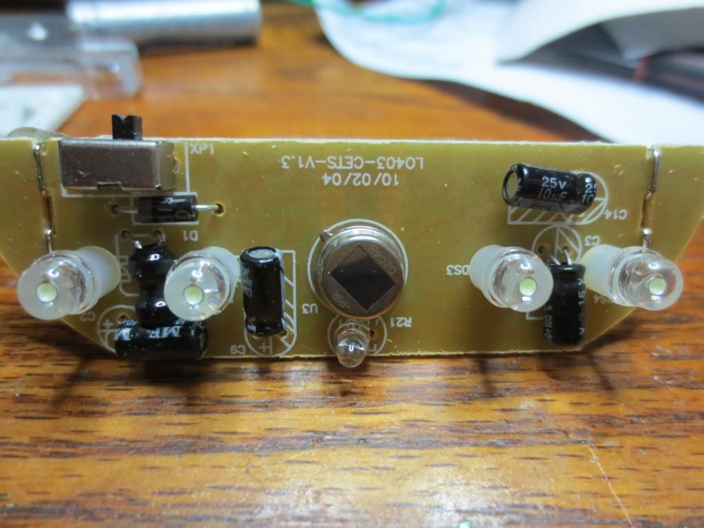
I found an interesting keyhole light circuit for about $4 on Ebay that uses PIR motion detection and 4 LED's running on ONE AA battery:
The 3 inch long case is meant to be mounted as a door key light. The motion sensor is in the middle behind a clear Fresnel lense.
Four bright white LED's put out plenty of light with just one battery. PIR sensors and bright LED's normally need 3 volts. The PIR only senses when you are close to the door.
Above there is a clear light sensing diode or transistor(base is run by light) below the center PIR infrared sensor to sense ambient room light.
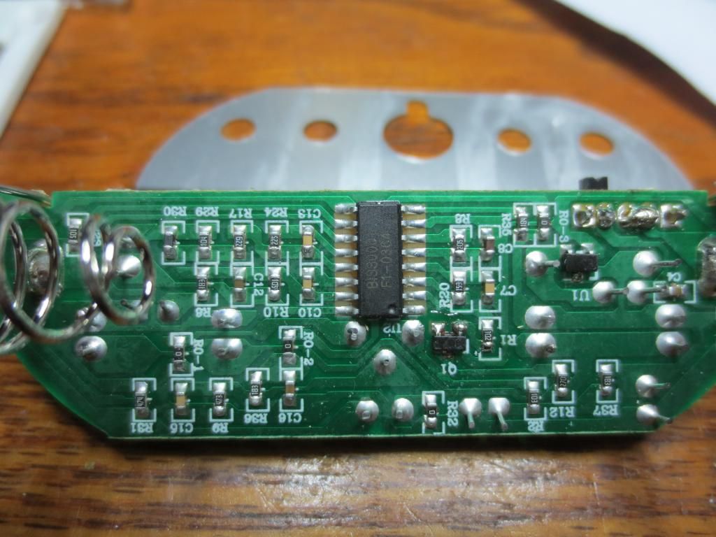
Plenty of surface components on the bottom make this circuit hard to imitate. A transistor probably makes a voltage doubler for a 3 volt regulator:
The display label sticker shown above the bottom of the board must be removed to slide out the circuit board. Peel it off carefully to replace it later.
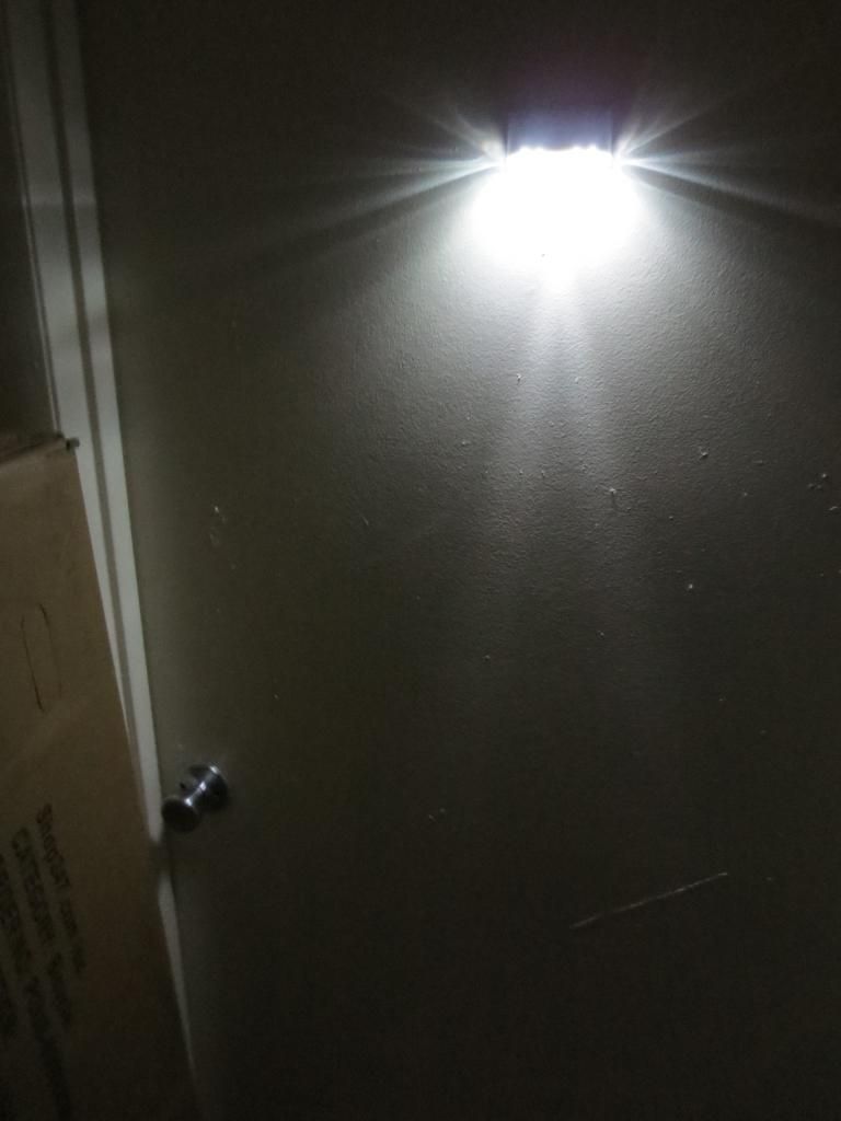
I have to walk up to the door and it senses me at about 2 feet away. It stays off when there is enough room light too!
I'm just going to leave it on the door to see how long the battery lasts. It should last a while as it does not come on when I walk by.
Search for Keyhole light on Ebay! Sells for over $8 on Amazon.
Please acknowledge and thank members who answer your questions!
QB64 is a FREE QBasic compiler for WIN, MAC(OSX) and LINUX : https://www.qb64.org/forum/index.php
Get my Q-Basics demonstrator: https://www.dropbox.com/s/fdmgp91d6h8ps ... s.zip?dl=0
QB64 is a FREE QBasic compiler for WIN, MAC(OSX) and LINUX : https://www.qb64.org/forum/index.php
Get my Q-Basics demonstrator: https://www.dropbox.com/s/fdmgp91d6h8ps ... s.zip?dl=0
Re: Solar panel charger with auto shutoff. Solar LED drivers.
Hi, I'm new to the forum but I am impressed on the quality of responces.
I was in the process of coverting a 99c solar light using a yx805 ic exactly like the one described here to use a 3.4 20ma color changing bulb. After trying to increase the voltage several different ways without changing the board added a boost module and the 3.4v led in place of the existing led. The modules are the ones sold One ebay . http://pages.ebay.com/link/?nav=item.vi ... 46&alt=web
It works like a charm except the light stays on all the time. I tried it on two units with the same result. If reverse the change and put the original led it works fine. The led does not light in the daytime and only when the solar panel receives no light. Any ideas to get this to work would be most appreciated.
- burger2227
- Veteran
- Posts: 2466
- Joined: Mon Aug 21, 2006 12:40 am
- Location: Pittsburgh, PA
Re: Solar panel charger with auto shutoff. Solar LED drivers.
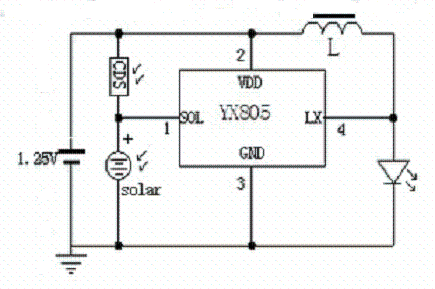
The yx805 chip already doubles voltage to LED's so a single battery produces 3 volts AC which the LED rectifies itself. Pin 1 controls the output from pin 4 to the LED and sends charging voltage to the battery when high enough. You can rectify low AC voltage to pin 1 and filter it with a small capacitor(1 to 10 uF) or use a solar panel voltage or an LDR (light dependent resistor, transistor or diode) from the battery to keep it off during the day.
Although the CDS(LDR) is shown with a solar panel, either can be used instead of both:
When pin 1 charging voltage goes low, the LED turns on until battery voltage goes below .9 volts.
You cannot use the output of pin 4 to run another chip reliably, just LED's! Flashing LED's won't blink either.
I fixed your link and removed the second post for you. You can edit your own posts here. Please limit links to advertisements to relevant topic items.
Please acknowledge and thank members who answer your questions!
QB64 is a FREE QBasic compiler for WIN, MAC(OSX) and LINUX : https://www.qb64.org/forum/index.php
Get my Q-Basics demonstrator: https://www.dropbox.com/s/fdmgp91d6h8ps ... s.zip?dl=0
QB64 is a FREE QBasic compiler for WIN, MAC(OSX) and LINUX : https://www.qb64.org/forum/index.php
Get my Q-Basics demonstrator: https://www.dropbox.com/s/fdmgp91d6h8ps ... s.zip?dl=0
Re: Solar panel charger with auto shutoff. Solar LED drivers.
Thanks for the response. My yx508 has 0128 below it. The voltage to the led is only 1.2 volts. If I put a 3.4 volts led it barely lights it. If I apply 3 volts to the same led directly it is much brighter. Does the chip itself suppose to increase then voltage or does the coil determine the final voltage. I am just learning about electronic.
Tim
Tim
- burger2227
- Veteran
- Posts: 2466
- Joined: Mon Aug 21, 2006 12:40 am
- Location: Pittsburgh, PA
Re: Solar panel charger with auto shutoff. Solar LED drivers.
You cannot really see the AC voltage applied to the LED when measuring DC. Only see the battery.
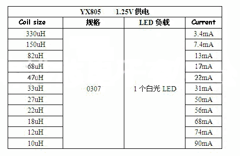
The value of the coil determines the current supplied to the LED('s):
Series LED's all get the same current, but less voltage, 2 in series get half the voltage.
Parallel LED's get less current, but same voltage, 2 in parallel get half the current, 4 get 1/4.
Most bright 3 volt LED's require about 20 ma for best brightness. I use 33 or 44 uH.
Coils that are pre-made are normally pale green with resistor color markings of micro Henry's.
Please acknowledge and thank members who answer your questions!
QB64 is a FREE QBasic compiler for WIN, MAC(OSX) and LINUX : https://www.qb64.org/forum/index.php
Get my Q-Basics demonstrator: https://www.dropbox.com/s/fdmgp91d6h8ps ... s.zip?dl=0
QB64 is a FREE QBasic compiler for WIN, MAC(OSX) and LINUX : https://www.qb64.org/forum/index.php
Get my Q-Basics demonstrator: https://www.dropbox.com/s/fdmgp91d6h8ps ... s.zip?dl=0
Re: Solar panel charger with auto shutoff. Solar LED drivers.
Thanks so much, so I just need to swap out the inducer with a 33 uh or 47 uh and it should work fine.
Re: Solar panel charger with auto shutoff. Solar LED drivers.
It look like yx508 will only produce 1.2 volts to the led no matter what I change. The inductor was already a 47 uf. I tried changing it and when down to 10 uf and theRe was no increase in voltage. I'm looked at another solor light that put out 2.4 from a 1.2 battery and it had then 5252 chip, a 11 uf inductor and a 104 capacitor. It would put out 2.4 volts for one led and 5.8 volts for two leds in series. I think this on is the ideal setup. So I can't see how I would convert an existing light using the yx508 to increase voltage without losing the auto shutoff.
- burger2227
- Veteran
- Posts: 2466
- Joined: Mon Aug 21, 2006 12:40 am
- Location: Pittsburgh, PA
Re: Solar panel charger with auto shutoff. Solar LED drivers.
You cannot see the extra voltage as it is AC, not DC. If your LED's are dull then they are the wrong kind or may need a higher powered circuit. The circuit is simple to make and I've never had a problem using a YX805 or a 5252F.
My pictures are proof enough!
Please acknowledge and thank members who answer your questions!
QB64 is a FREE QBasic compiler for WIN, MAC(OSX) and LINUX : https://www.qb64.org/forum/index.php
Get my Q-Basics demonstrator: https://www.dropbox.com/s/fdmgp91d6h8ps ... s.zip?dl=0
QB64 is a FREE QBasic compiler for WIN, MAC(OSX) and LINUX : https://www.qb64.org/forum/index.php
Get my Q-Basics demonstrator: https://www.dropbox.com/s/fdmgp91d6h8ps ... s.zip?dl=0
Re: Solar panel charger with auto shutoff. Solar LED drivers.
I believe you. I am really new at this. I will double check everything and try it again.
- burger2227
- Veteran
- Posts: 2466
- Joined: Mon Aug 21, 2006 12:40 am
- Location: Pittsburgh, PA
Re: Solar panel charger with auto shutoff. Solar LED drivers.
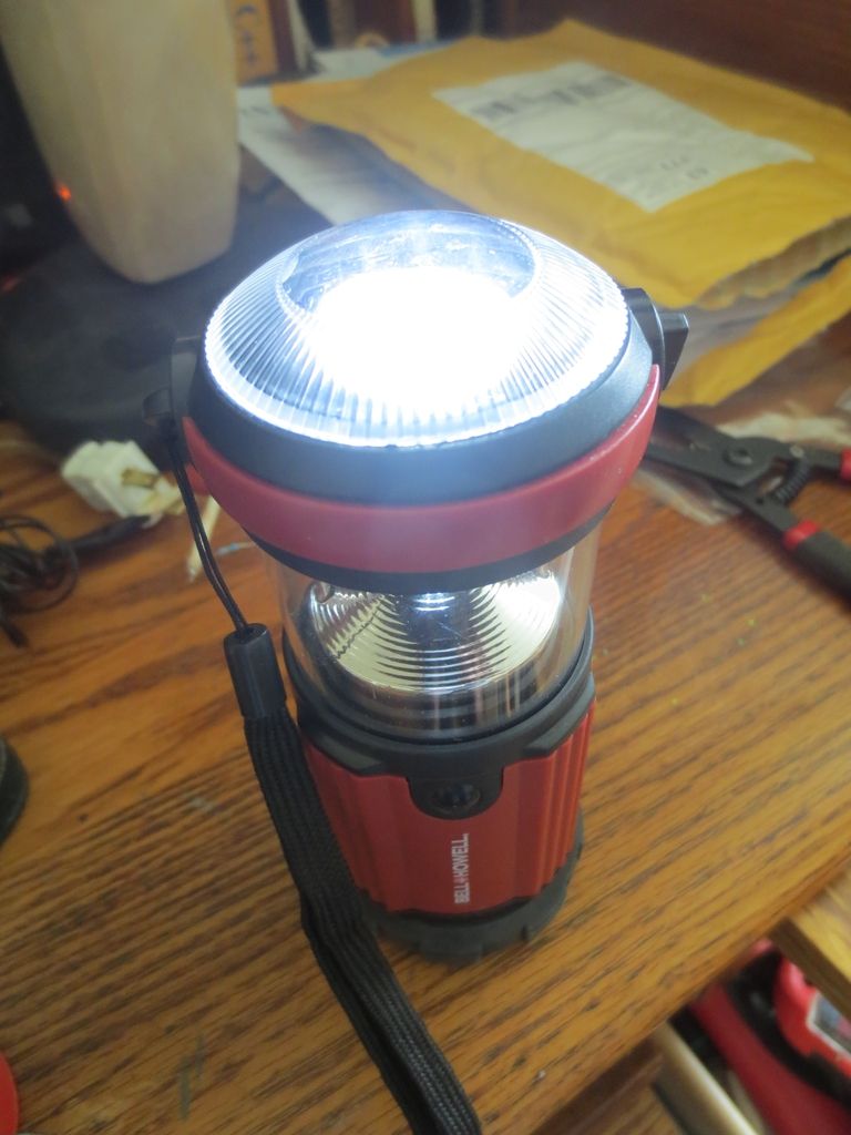
To show the versatility of the solar LED chips, I was able to run a 6 volt, 4 AA battery lantern with just 2 AA batteries:
The LED's on top can be rotated to shine up or down on a cone deflector with two levels of brightness and a flashing mode.
Even with the 5252 circuit, it had 2 levels and flashing mode. I just couldn't turn it off. So the chip can create
6 volts! If the chip circuit can be wired internally then perhaps the on/off switch can cut off the chip ground
to keep it turned off.
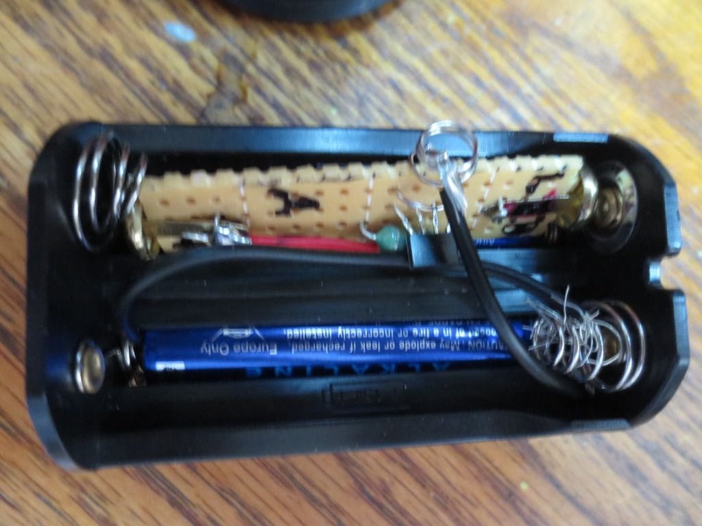
I had previously made a AA battery eliminator with a 5252F chip so I could swap it for the first positive battery going directly to the LED's:
The eliminator goes in the top positive end and the last battery is jumpered out with a black wire to the
negative block end on right. The chip requires a ground from a side spring so I jumpered it to ground on
the negative end also which sadly bypasses the switch.
2 AA batteries follow to supply 3 volts to the circuit in the other half of the battery pack.
The 5252F will double that voltage!
This can only be a temporary circuit as the chip ground is not switched off by the lantern and it would drain it if left in permanently!
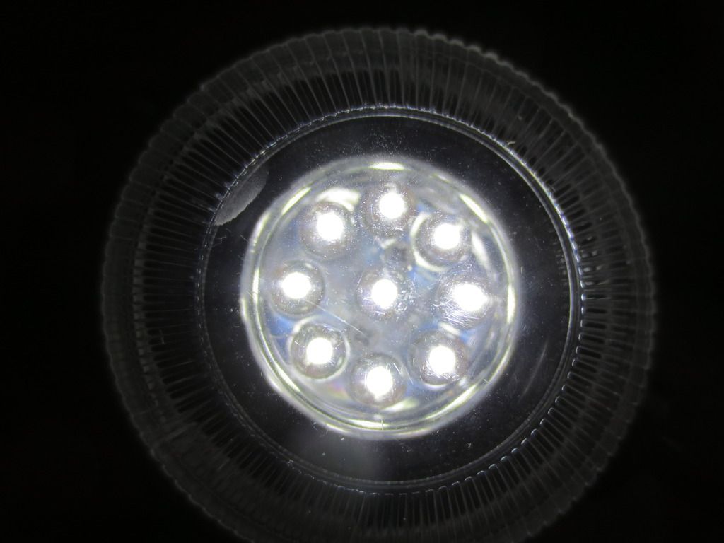
9 LED's! It just proves that the chip can be used to replace half of 2 or 4 battery LED lamps. 3 battery
ones would be dimmer but possible too. Remember that the coil sets the LED current. 20 to 30 ma is best
for all BRIGHT LED's! Red, yellow and green normal LED's may burn out as they need less current!
PS: The photograph above does not show how bright the 9 LED's really are!
Please acknowledge and thank members who answer your questions!
QB64 is a FREE QBasic compiler for WIN, MAC(OSX) and LINUX : https://www.qb64.org/forum/index.php
Get my Q-Basics demonstrator: https://www.dropbox.com/s/fdmgp91d6h8ps ... s.zip?dl=0
QB64 is a FREE QBasic compiler for WIN, MAC(OSX) and LINUX : https://www.qb64.org/forum/index.php
Get my Q-Basics demonstrator: https://www.dropbox.com/s/fdmgp91d6h8ps ... s.zip?dl=0
- burger2227
- Veteran
- Posts: 2466
- Joined: Mon Aug 21, 2006 12:40 am
- Location: Pittsburgh, PA
Re: Solar panel charger with auto shutoff. Solar LED drivers.
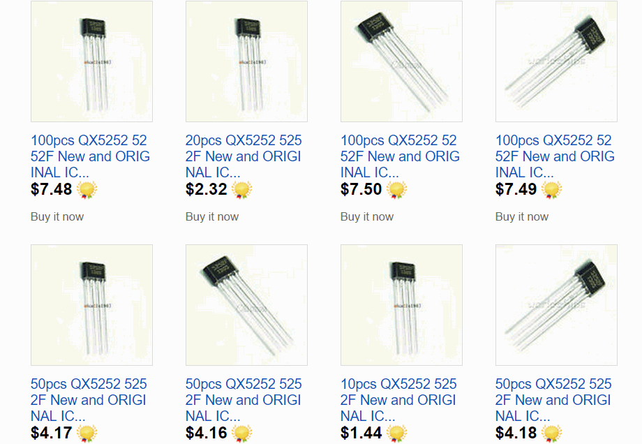
Latest prices on Ebay plus $1.98 shipping for 10 to 100 from China:
Can take up to a month for delivery, but most are reliable. Claims will resend them.
Other sellers are from USA for slightly higher, but faster, so I think I started it all last year selling cheaper!
Originally I paid $30 for 100 from the cheapest seller including the $10 shipping from Hong Kong.
I sold half of them to get my money back, but my shipping was $3 and much faster in USA.
Please acknowledge and thank members who answer your questions!
QB64 is a FREE QBasic compiler for WIN, MAC(OSX) and LINUX : https://www.qb64.org/forum/index.php
Get my Q-Basics demonstrator: https://www.dropbox.com/s/fdmgp91d6h8ps ... s.zip?dl=0
QB64 is a FREE QBasic compiler for WIN, MAC(OSX) and LINUX : https://www.qb64.org/forum/index.php
Get my Q-Basics demonstrator: https://www.dropbox.com/s/fdmgp91d6h8ps ... s.zip?dl=0
- burger2227
- Veteran
- Posts: 2466
- Joined: Mon Aug 21, 2006 12:40 am
- Location: Pittsburgh, PA
Re: Solar panel charger with auto shutoff. Solar LED drivers.
Found out that the 5252F drive shuts off at .9 volts to avoid LED blinking.
While it also protects NICAD batteries from being over discharged constantly every day!
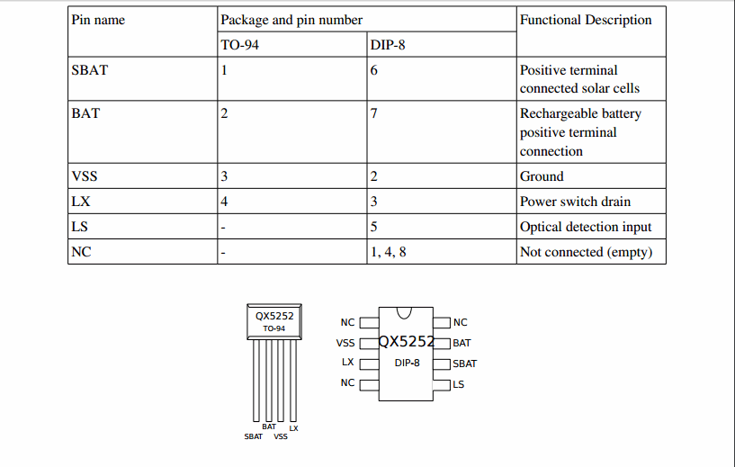
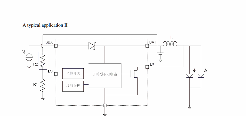
Recently found another solar LED driver QX5252E in a DIP-8 pin package (not surface mount):
The chip has an LS pin 5 that can use a LDR light sensing resistor or diode, but must also have a ground
resistance not found necessary with the 4 pin TO-94 package. DIP 8 Pins 1, 4 and 8 have no connections:
A solar panel charge voltage can be replaced with trickle voltage at battery voltages with a ground resistor.
PDF for QX5252F: TO-94 and QX5252E: DIP-8
Flashlights or other switched devices won't even require a rechargeable battery without pin 6 used.
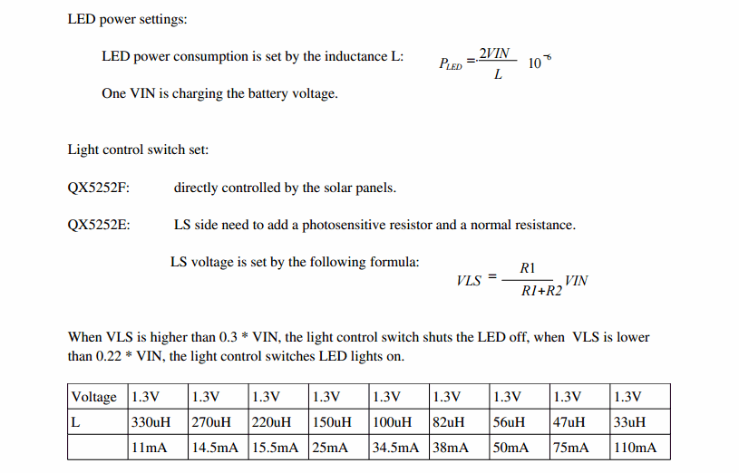
VIN is the battery voltage used. The solar or charging voltage would require a slightly higher voltage.
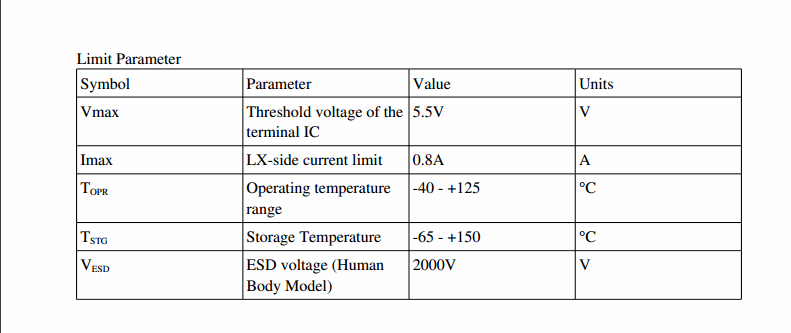
Up to 3 alkaline 1.5 volt or 4 rechargeable 1.2 volt batteries can drive the LED circiuit, 5 volts max:
Maximum current is 800 ma. Don't push that limit! LED current is determined by battery voltage and coil size.
So far my power failure outlet batteries have lasted 3 years!
Please acknowledge and thank members who answer your questions!
QB64 is a FREE QBasic compiler for WIN, MAC(OSX) and LINUX : https://www.qb64.org/forum/index.php
Get my Q-Basics demonstrator: https://www.dropbox.com/s/fdmgp91d6h8ps ... s.zip?dl=0
QB64 is a FREE QBasic compiler for WIN, MAC(OSX) and LINUX : https://www.qb64.org/forum/index.php
Get my Q-Basics demonstrator: https://www.dropbox.com/s/fdmgp91d6h8ps ... s.zip?dl=0