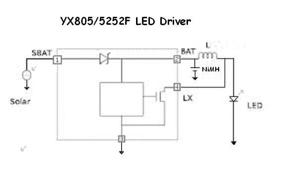
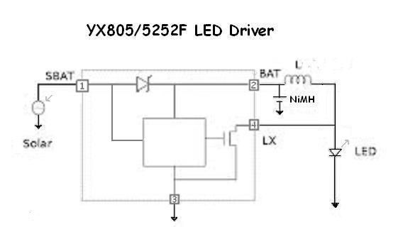
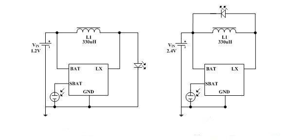
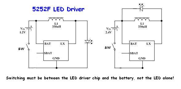
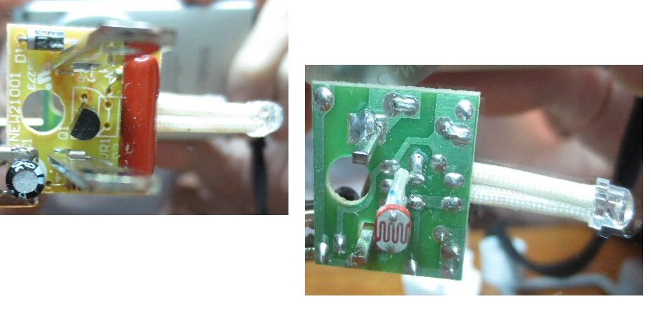
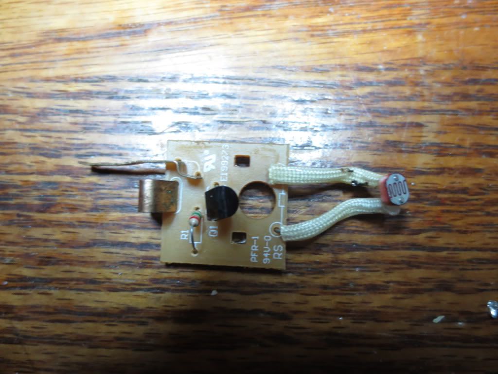
Solar panel charger with auto shutoff. Solar LED drivers.
Posted: Fri Jun 14, 2013 9:37 am
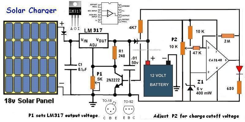
Circuit monitors a battery being charged using a LM317T or LM338T TO 220 type voltage regulator:
LM317SolarCharger-2.jpg
A cheaper BC547 transistor can be substituted for the 2N2222 which cuts off charging voltage
When the battery voltage reaches a fully charged voltage set by P2, the Op Amp turns off the voltage
regulator. This circuit is similar to the tool charger circuit except that the op amp is driven by the battery as
a solar panel cannot be counted on to supply a steady voltage. Normally voltages will go up and down with
the brightness. The regulator should deliver the same current, but limit the voltage supplied to the battery
to 14 volts.
The voltage regulator may need a heat sink if it gets too hot to touch and could melt a breadboard!
Locate the voltage regulator on a PC board near an outside edge so that a heat sink can be easily added.
Tool charger circuit with circuit layout
The Shottkey diodes on both sides of the regulator protect it from reverse currents and the one on the output
keeps the battery from being drained when the transistor shuts the regulator off. Shottkey diodes drop less
voltage across them.
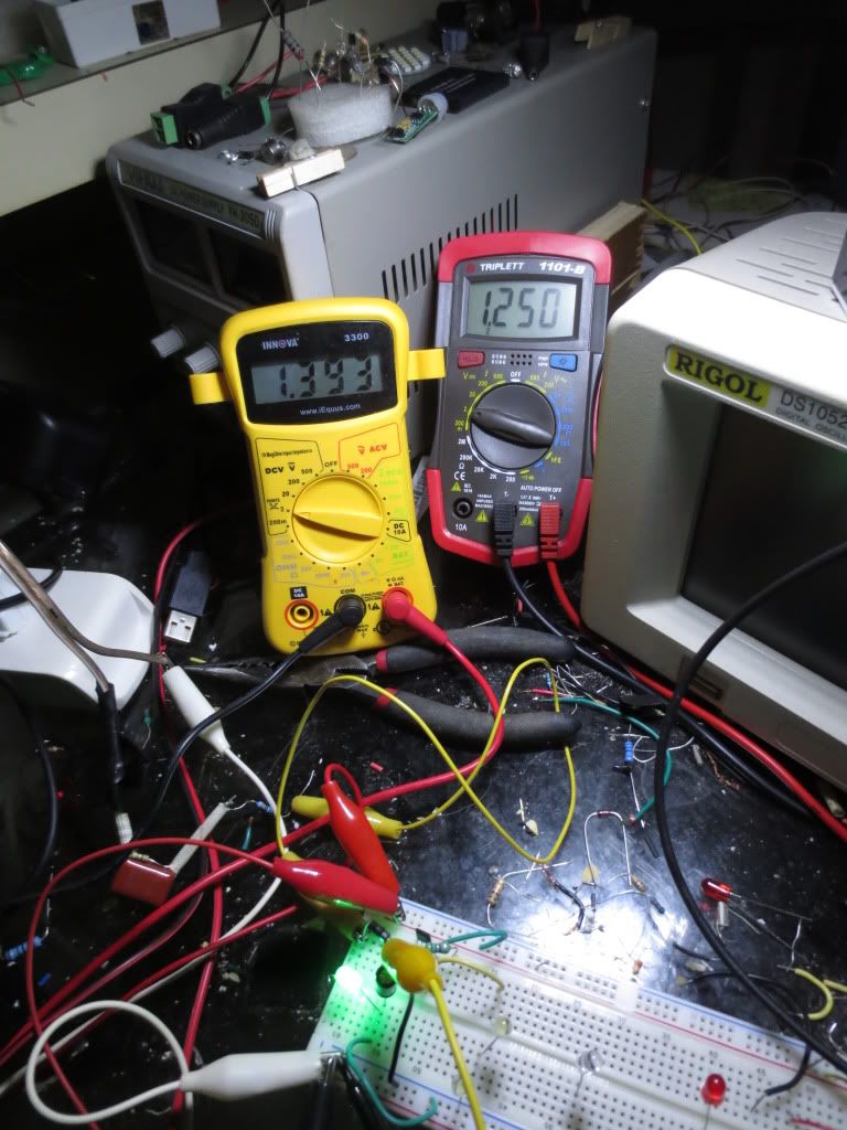
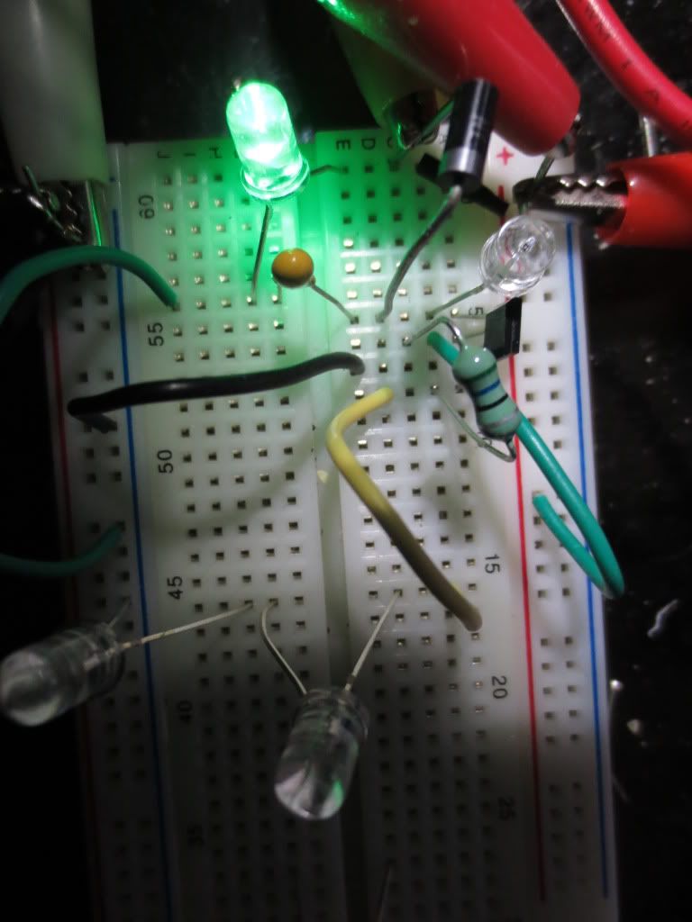
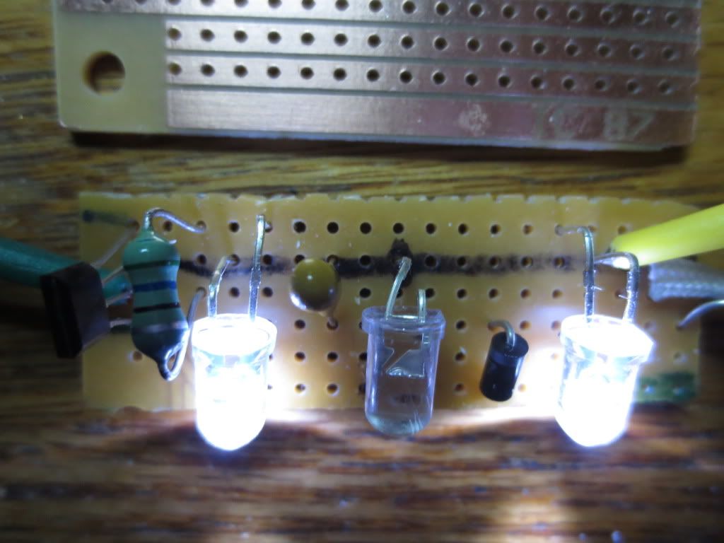
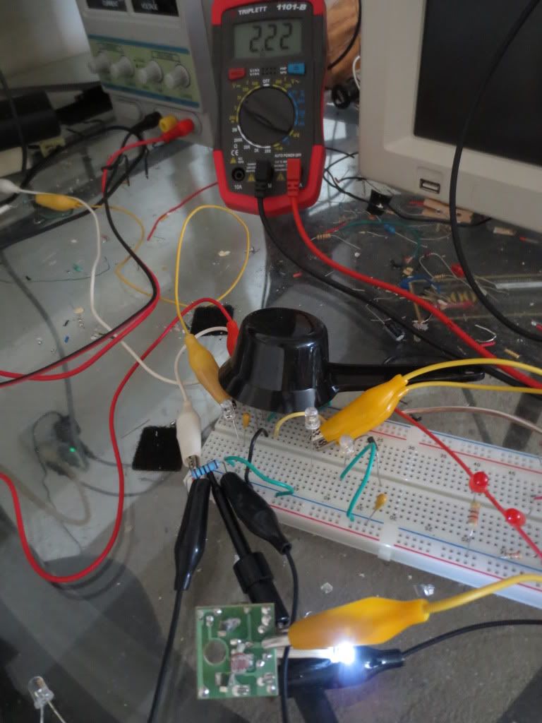
I tested this circuit in my car for a week and the battery voltage never got high enough to cause any damage:
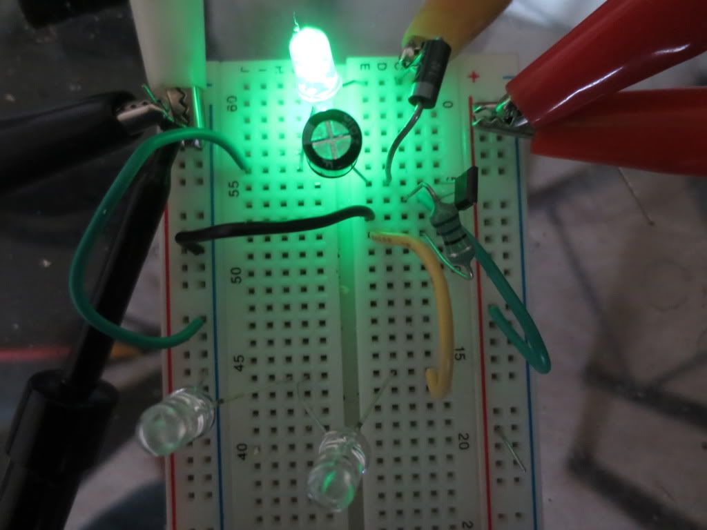
CA3140on.jpg
Two 470 ohm in parallel for 235 ohm and two 4.7K in parallel for 2.3K on the regulator adjust to get 13.6 volts.
Adjust P1 to Set the regulator voltage on the output diode cathode to 14 volts without connecting it to
the battery. Use a power supply or the solar cell input voltage greater than 16 volts in full sun with a load on
the regulator output where the battery will be. An LED and resistor can be used as the load. The battery will
pull the output voltage down when it is connected to the cathode of the output diode.
Voltage Regulator Calculator
Once the regulator is set, connect the battery through a male cigarette type adapter plug or battery clamps.
When the battery voltage approaches 13 volts, set P2 so that the LED comes on then turn the pot the
other way a bit. The LED should stay on until the battery voltage drops about 1/2 volt due to the 2M and 47K
resistance feedback from the Op Amp. This also keeps the op amp from oscillating on and off!
This circuit can also be used to charge other voltage batteries:
P1 can be 2K for voltages from 6 to 10 volts, 5K for up to 28 volts. Output should be set for battery + 1/6 volts.
P2 can be any value up to 250K to reduce battery drain.
Z1 should be a Zener diode rated at about half of the battery voltage.
Op Amp most any kind. Increase the 2M resistor to reduce the voltage spread between shutoff and back on.
A cheaper BC547 transistor can be substituted for the 2N2222
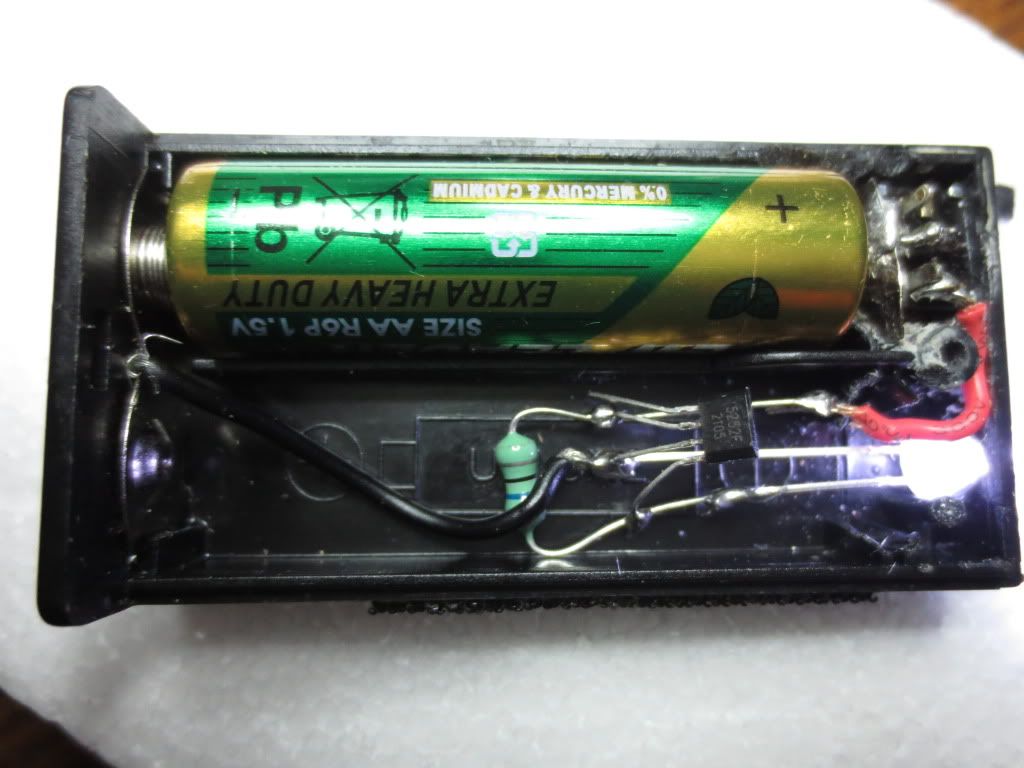
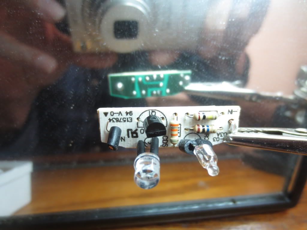
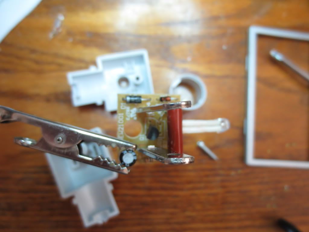
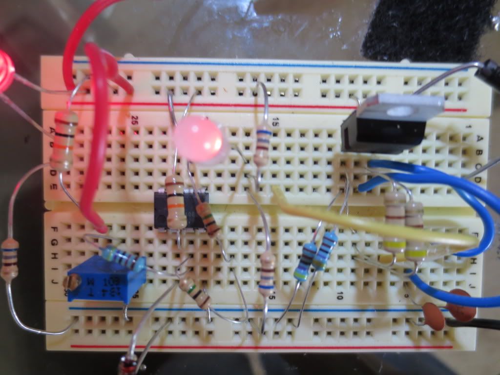
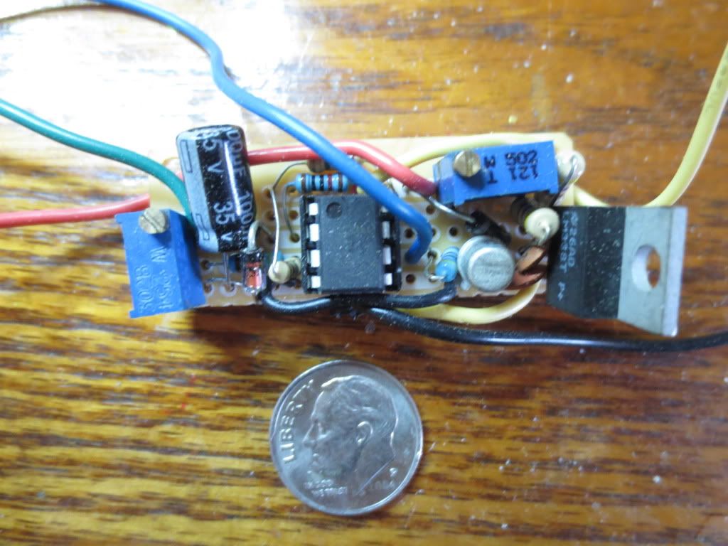
Here is the above circuit I made to control the charging of a 12 volt hand vacuum:
12voltCharger.jpg
Yellow to charging input AFTER the diode in the tool if the charger is AC. Add a diode when necessary.
Black to common which should be black in most tools. Only one common connection should be required.
Blue to the indicator LED + anode(long leg). A current resistor should also be in series to common.
Red to the + battery. Regulator voltage output can also be read before connecting to battery
Green normally to the battery with the red wire. Can also jumper to the input voltage when testing the
cutoff circuit without a battery.
To set the LM338 Output voltage: With volt meter on red and black and input to yellow, adjust the
5K trimmer to 1 + 1/6 battery voltage. Once set, the output voltage on the red wire should not vary.
The rectified charging voltage coming in to the regulator will normally be much higher than battery voltage.
The charger current should remain the same as the current the charger delivered previously.
To set the battery Cutoff voltage, connect the yellow wire to the input voltage and connect the
red and green wires to the positive battery. Adjust as necessary to the fully charged battery voltage.
When the red LED turns on, adjust the trimmer back down a half turn on a 25 turn trimmer. This may take
several adjustments to work properly!
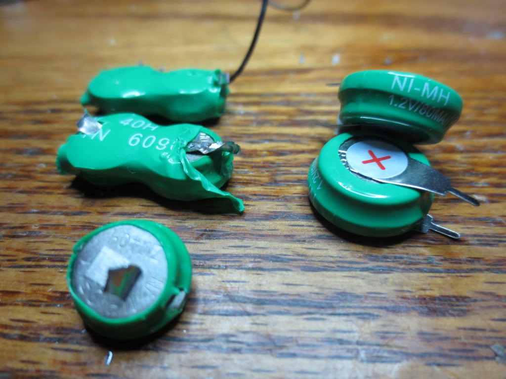
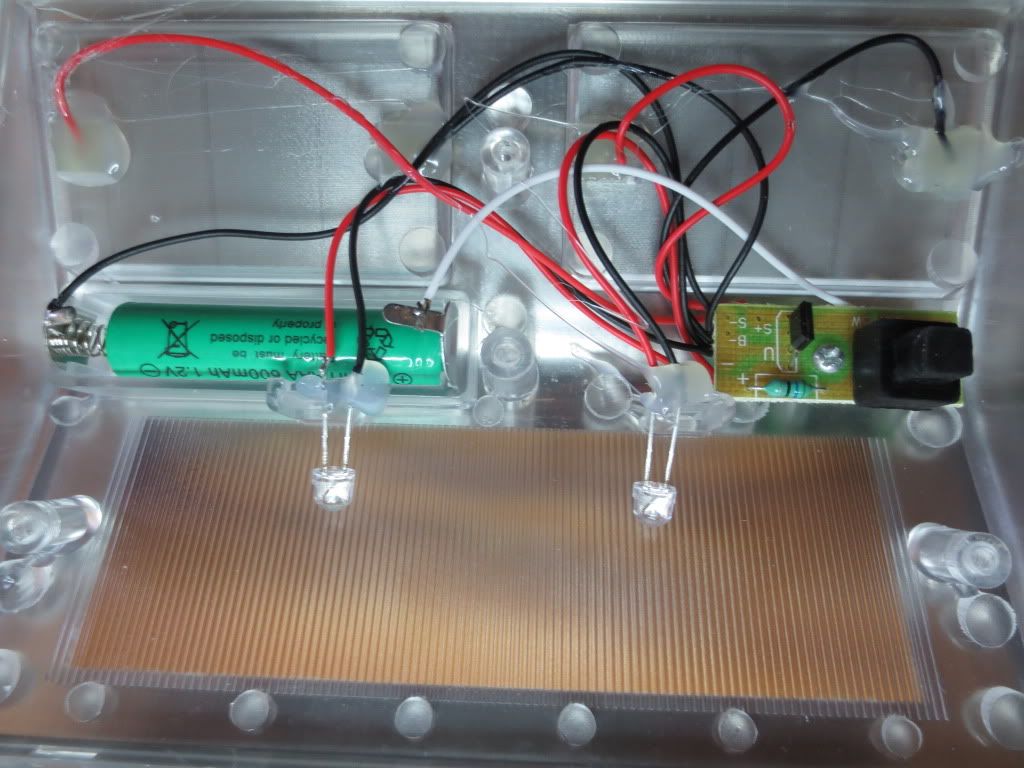
When the rechargeable NiCad batteries die, I plan to replace them with 3 Lithium batteries for 11.1 volts.
I will need to keep the voltage to 12 volts max for the 3 lithium pack charging circuit.
LM317SolarCharger-2.jpg
A cheaper BC547 transistor can be substituted for the 2N2222 which cuts off charging voltage
When the battery voltage reaches a fully charged voltage set by P2, the Op Amp turns off the voltage
regulator. This circuit is similar to the tool charger circuit except that the op amp is driven by the battery as
a solar panel cannot be counted on to supply a steady voltage. Normally voltages will go up and down with
the brightness. The regulator should deliver the same current, but limit the voltage supplied to the battery
to 14 volts.
The voltage regulator may need a heat sink if it gets too hot to touch and could melt a breadboard!
Locate the voltage regulator on a PC board near an outside edge so that a heat sink can be easily added.
Tool charger circuit with circuit layout
The Shottkey diodes on both sides of the regulator protect it from reverse currents and the one on the output
keeps the battery from being drained when the transistor shuts the regulator off. Shottkey diodes drop less
voltage across them.
I tested this circuit in my car for a week and the battery voltage never got high enough to cause any damage:
CA3140on.jpg
Two 470 ohm in parallel for 235 ohm and two 4.7K in parallel for 2.3K on the regulator adjust to get 13.6 volts.
Adjust P1 to Set the regulator voltage on the output diode cathode to 14 volts without connecting it to
the battery. Use a power supply or the solar cell input voltage greater than 16 volts in full sun with a load on
the regulator output where the battery will be. An LED and resistor can be used as the load. The battery will
pull the output voltage down when it is connected to the cathode of the output diode.
Voltage Regulator Calculator
Once the regulator is set, connect the battery through a male cigarette type adapter plug or battery clamps.
When the battery voltage approaches 13 volts, set P2 so that the LED comes on then turn the pot the
other way a bit. The LED should stay on until the battery voltage drops about 1/2 volt due to the 2M and 47K
resistance feedback from the Op Amp. This also keeps the op amp from oscillating on and off!
This circuit can also be used to charge other voltage batteries:
P1 can be 2K for voltages from 6 to 10 volts, 5K for up to 28 volts. Output should be set for battery + 1/6 volts.
P2 can be any value up to 250K to reduce battery drain.
Z1 should be a Zener diode rated at about half of the battery voltage.
Op Amp most any kind. Increase the 2M resistor to reduce the voltage spread between shutoff and back on.
A cheaper BC547 transistor can be substituted for the 2N2222
Here is the above circuit I made to control the charging of a 12 volt hand vacuum:
12voltCharger.jpg
Yellow to charging input AFTER the diode in the tool if the charger is AC. Add a diode when necessary.
Black to common which should be black in most tools. Only one common connection should be required.
Blue to the indicator LED + anode(long leg). A current resistor should also be in series to common.
Red to the + battery. Regulator voltage output can also be read before connecting to battery
Green normally to the battery with the red wire. Can also jumper to the input voltage when testing the
cutoff circuit without a battery.
To set the LM338 Output voltage: With volt meter on red and black and input to yellow, adjust the
5K trimmer to 1 + 1/6 battery voltage. Once set, the output voltage on the red wire should not vary.
The rectified charging voltage coming in to the regulator will normally be much higher than battery voltage.
The charger current should remain the same as the current the charger delivered previously.
To set the battery Cutoff voltage, connect the yellow wire to the input voltage and connect the
red and green wires to the positive battery. Adjust as necessary to the fully charged battery voltage.
When the red LED turns on, adjust the trimmer back down a half turn on a 25 turn trimmer. This may take
several adjustments to work properly!
When the rechargeable NiCad batteries die, I plan to replace them with 3 Lithium batteries for 11.1 volts.
I will need to keep the voltage to 12 volts max for the 3 lithium pack charging circuit.


