Each transistor setup conducts when the signal is not present to supply battery voltage to Pin 1 even if the CDS voltage is low.
The setup also allows higher voltage signals to be sent just by turning the transistors off.
The CDS control and Pin 1 capacitor are optional for various requirements. A 10 uF capacitor will delay the turn on time!
I tested the high signal circuit by sending @ 2.5 volts to the PNP transistor to turn it off with a PIR motion sensor module.
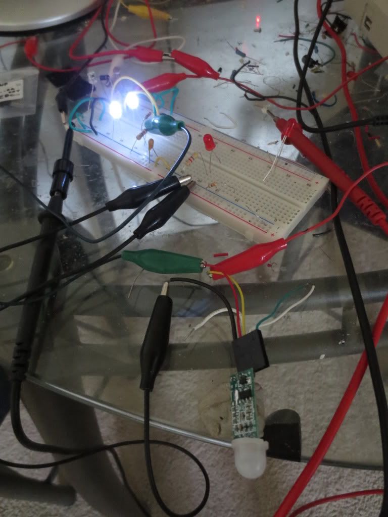
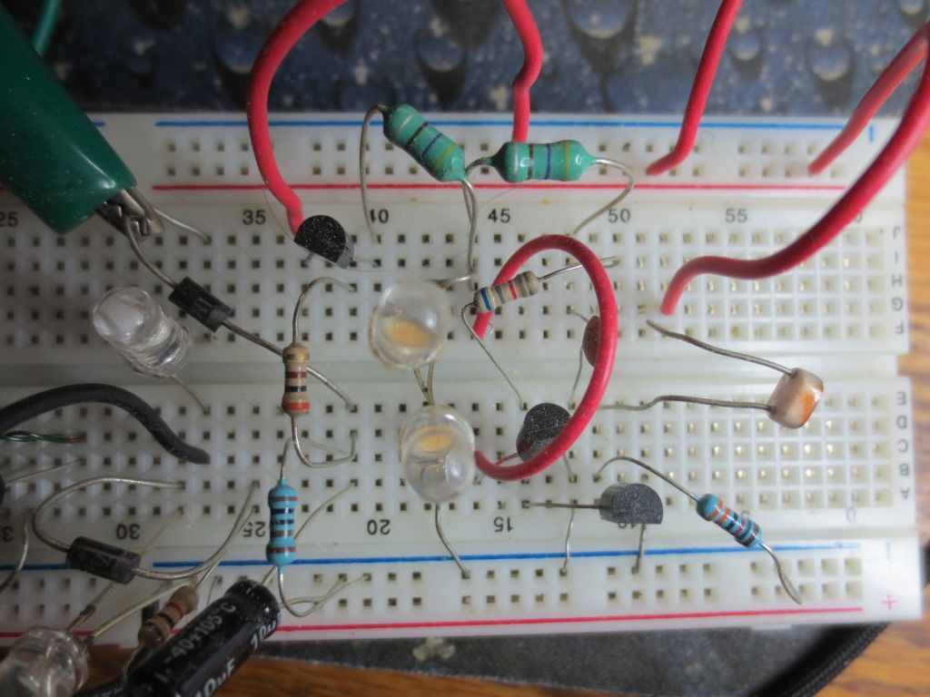
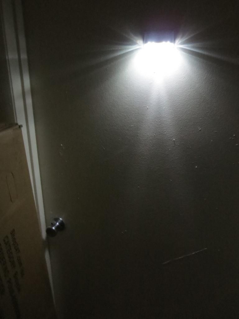
The CDS voltage becomes the only thing deciding if the LED driver should run or stay off. When it is dark,
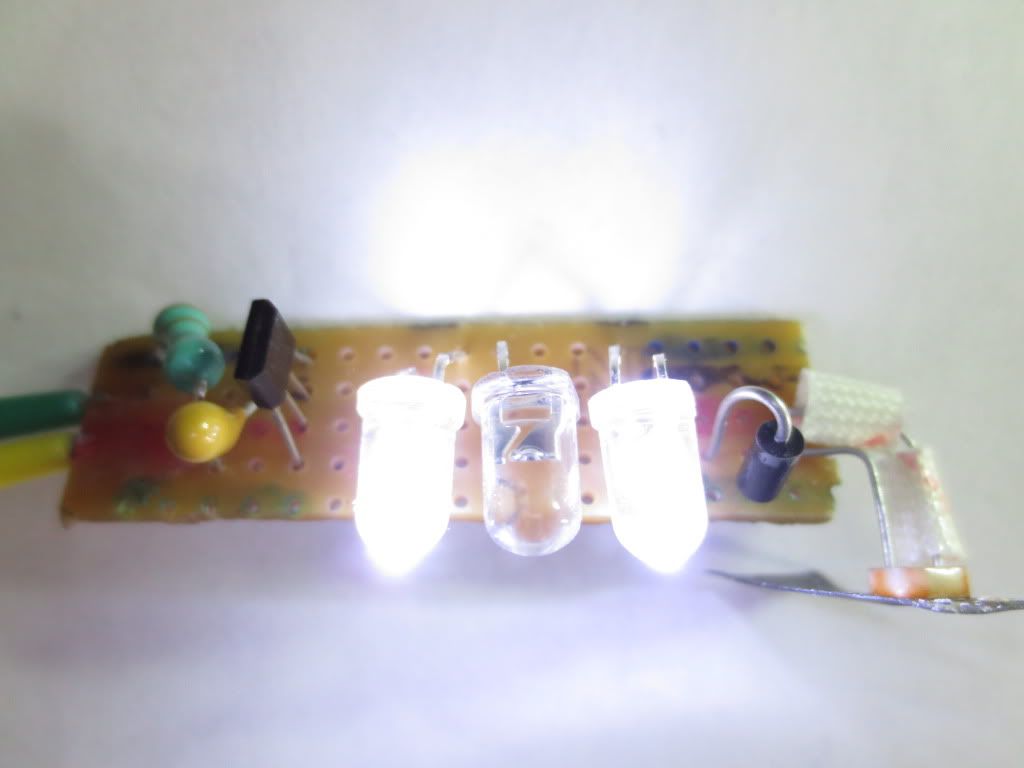
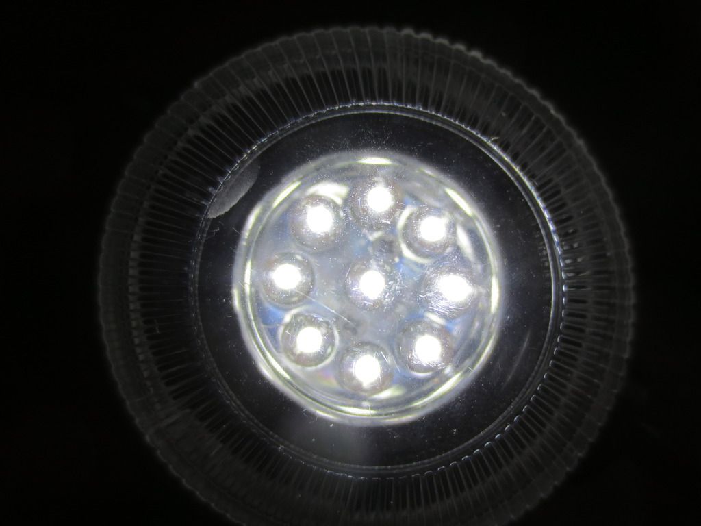
the LED's will come on with movement, but since the photocell is facing straight up, my shadow was enough
to allow them to light up.
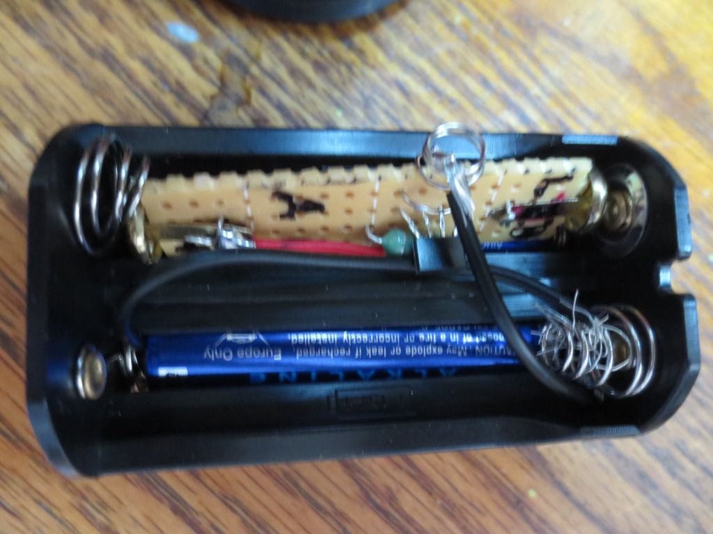
I kept the LED driver voltage to one battery and did not need any resistance from the battery to the transistor
with that low a voltage. I used a power supply to run the PIR sensor module because it needed 3.5 volts to work at all.