I found 2 returnable cameras, one was easy with tabs to take it apart and one was not so nice.
Now comes the hard part. Taking apart the camera and finding what you need:
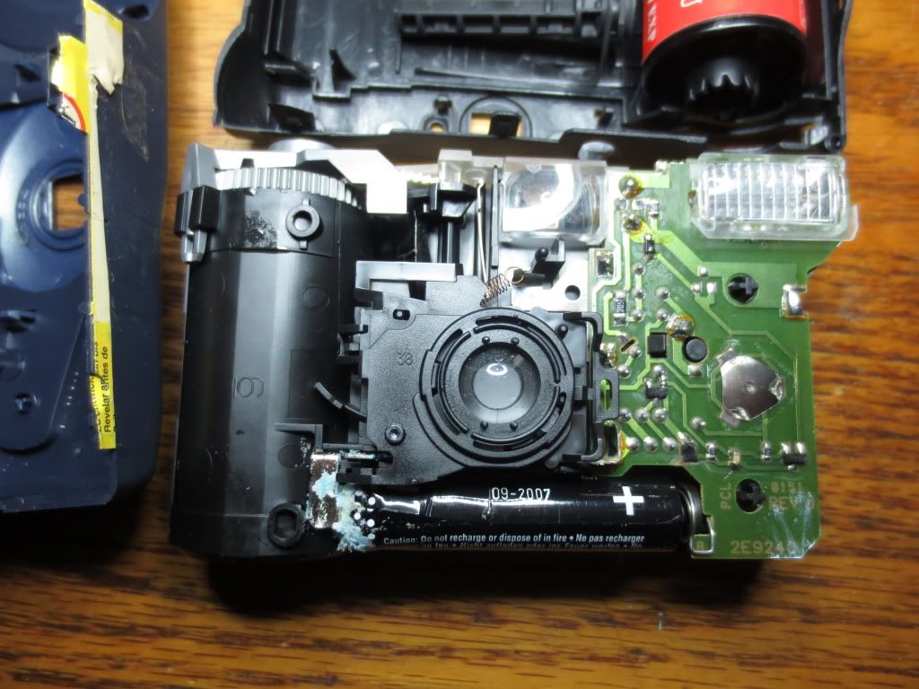
Note the pushbutton in the center. on the center board. That shiny button will need to be scraped off so that it
can be jumpered to run the 300 volt oscillating circuit. That pre-charges the flash capacitor which will be the
first thing to get rid of!
WARNING! Voltages inside the camera can exceed 1000 volts! 200 volts with no battery connection!
Also watch out for contact with the large electrolytic capacitor inside! It can hold 200 volts!
The voltage may not kill you, but people have died from impacts with objects when they react!
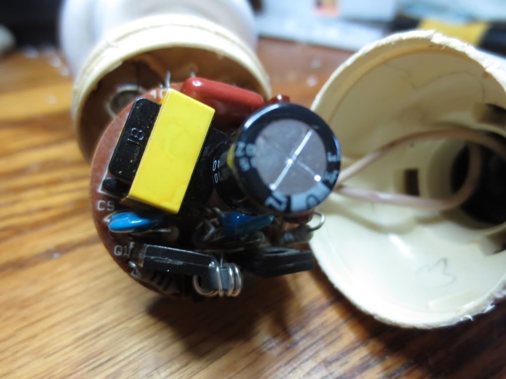
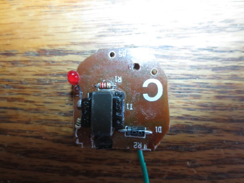
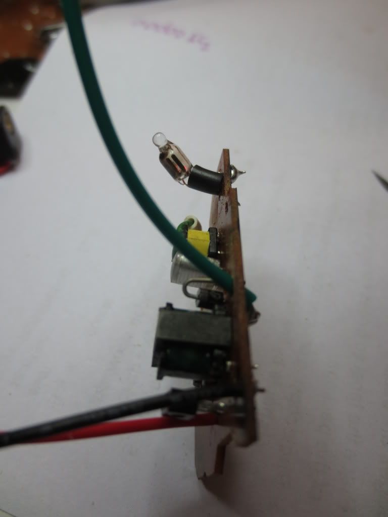
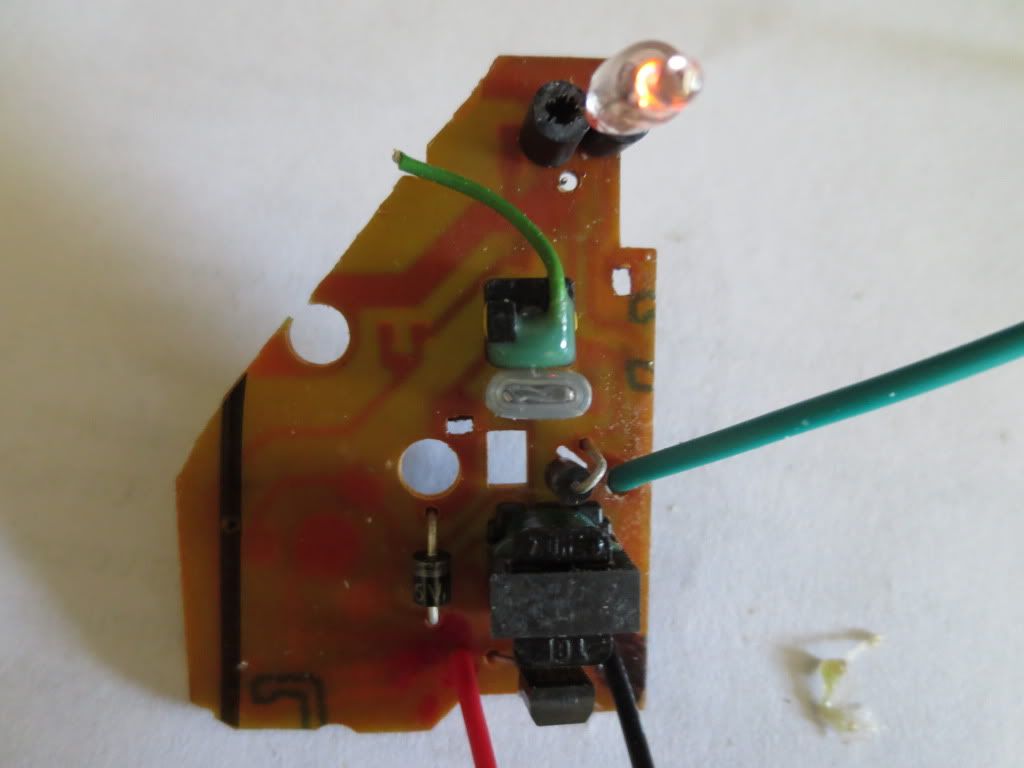
This one had a bad neon bulb so I replaced it with one from a night light outlet box. Our transformer is next to the
alligator clip along with the transistor and diode to left of it. Oddly this camera flash uses positive voltages too:
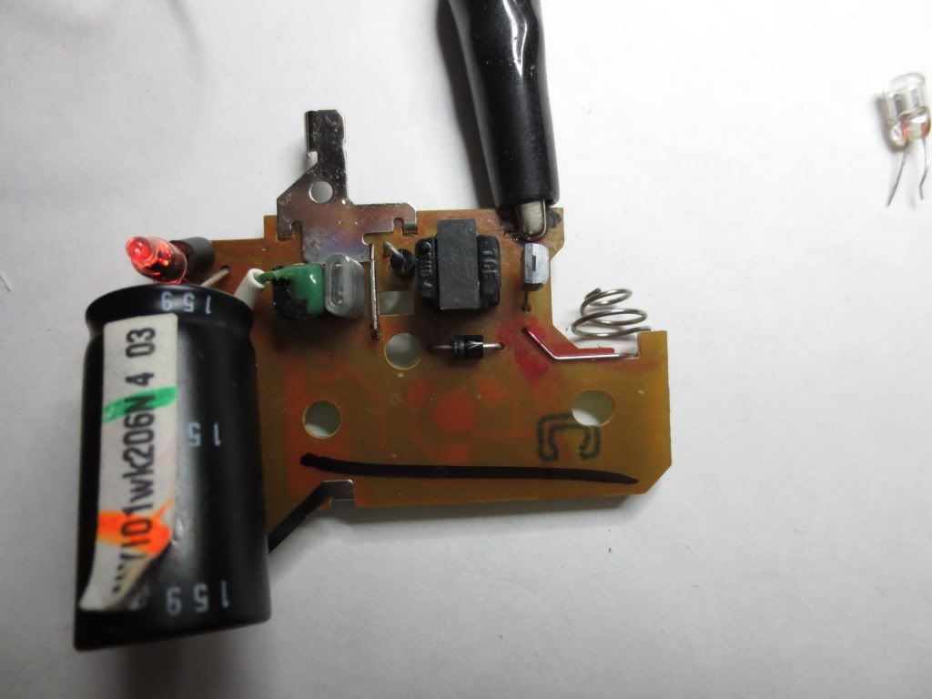
The neon bulb indicates charge voltage on the capacitor, but unfortunately it does not drain it all off over time.
Once the neon stops conducting, all of the rest of the voltage can stay there a long time and it is enough to
spark loudly and give you a jolt! I have seen some cameras that have high value resistors to drain them slowly.
Once the capacitor is removed, the neon bulb should glow whenever the 300 volt oscillator is running!
The center button is jumpered to run the oscillator all of the time but I see other problems nearby :
This board has problems as far as size because it has two surface mount transistors, one under our transformer
and one clear up near the top right of the circuit board. Not sure how they are involved in the circuit.
Note: The charging capacitor can spark, shock and burn tools and skin! Carefully jumper it with a 1 meg resistor.
The second camera was a smaller fit! The 200 volt transformer is easy to find, but it could have components anywhere too:
Also there is a transistor and diode that will be needed as well as any resistors and capacitors nearby.
What we don't need is the green coil off to the right because it further boosts voltage up to 1000 volts or more!
The bare wire going to the flash bulb plate can deliver that voltage directly to you!
Hopefully the picture taking button is broken by now! The flash button just charges it up.[/b]
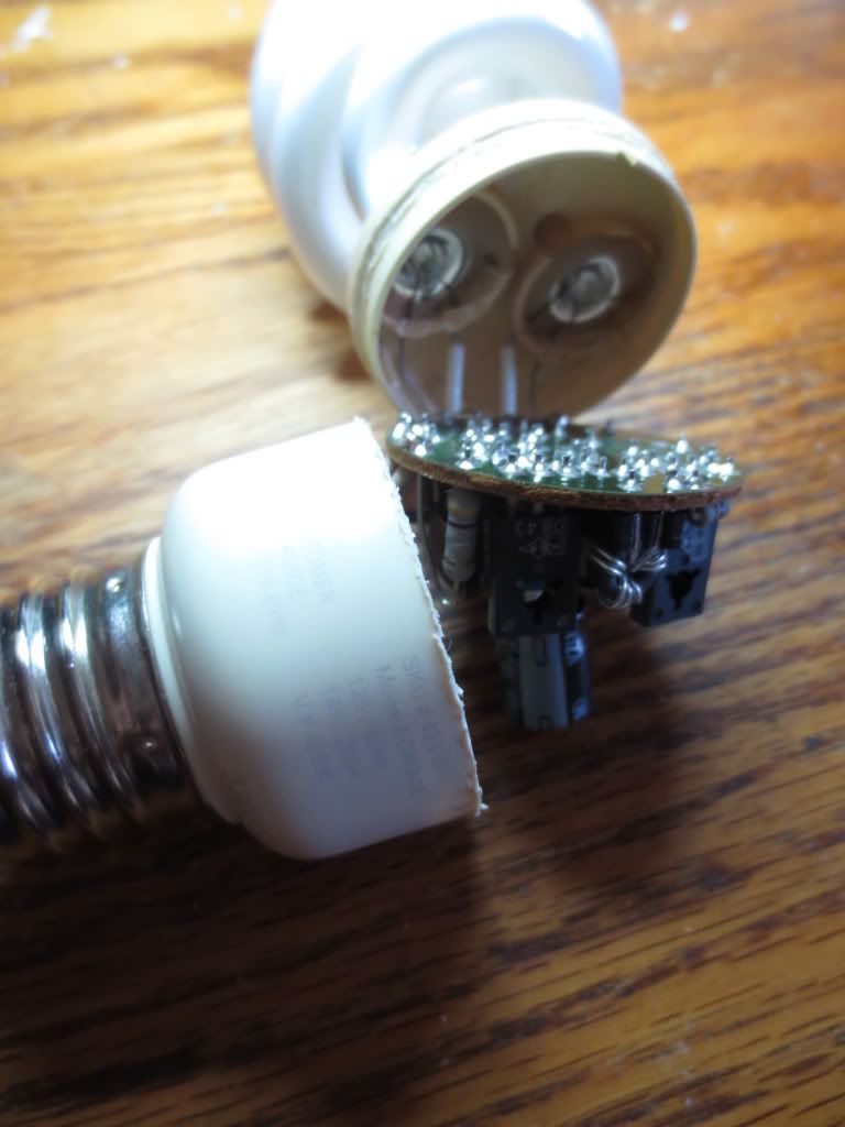
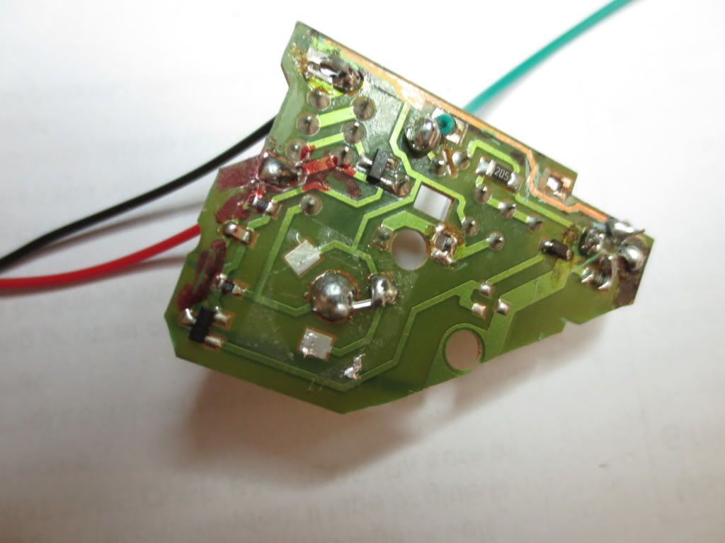
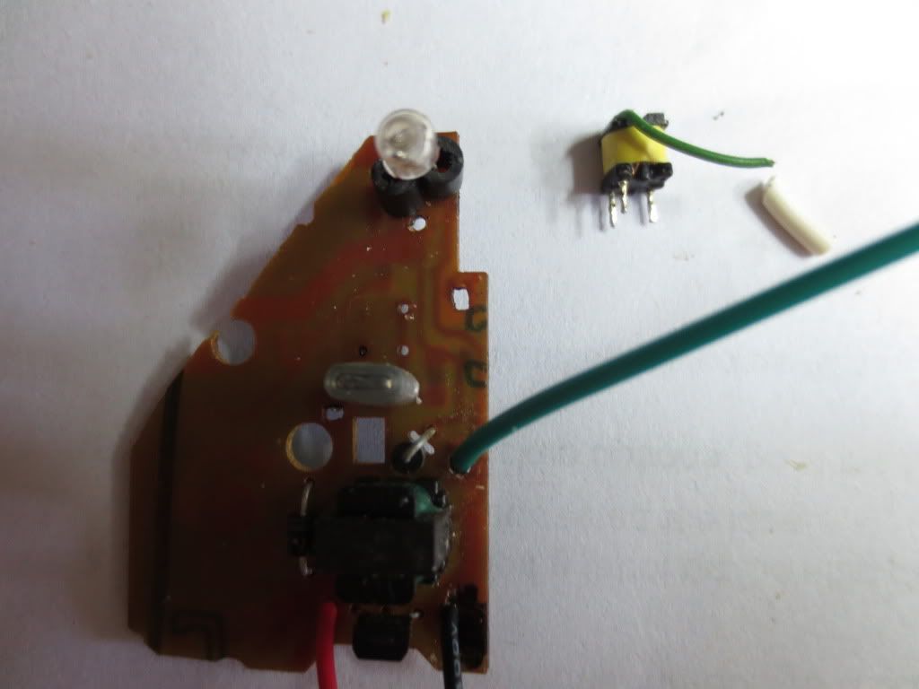
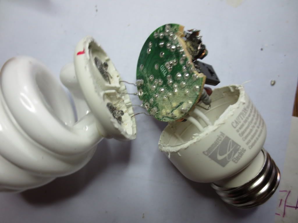
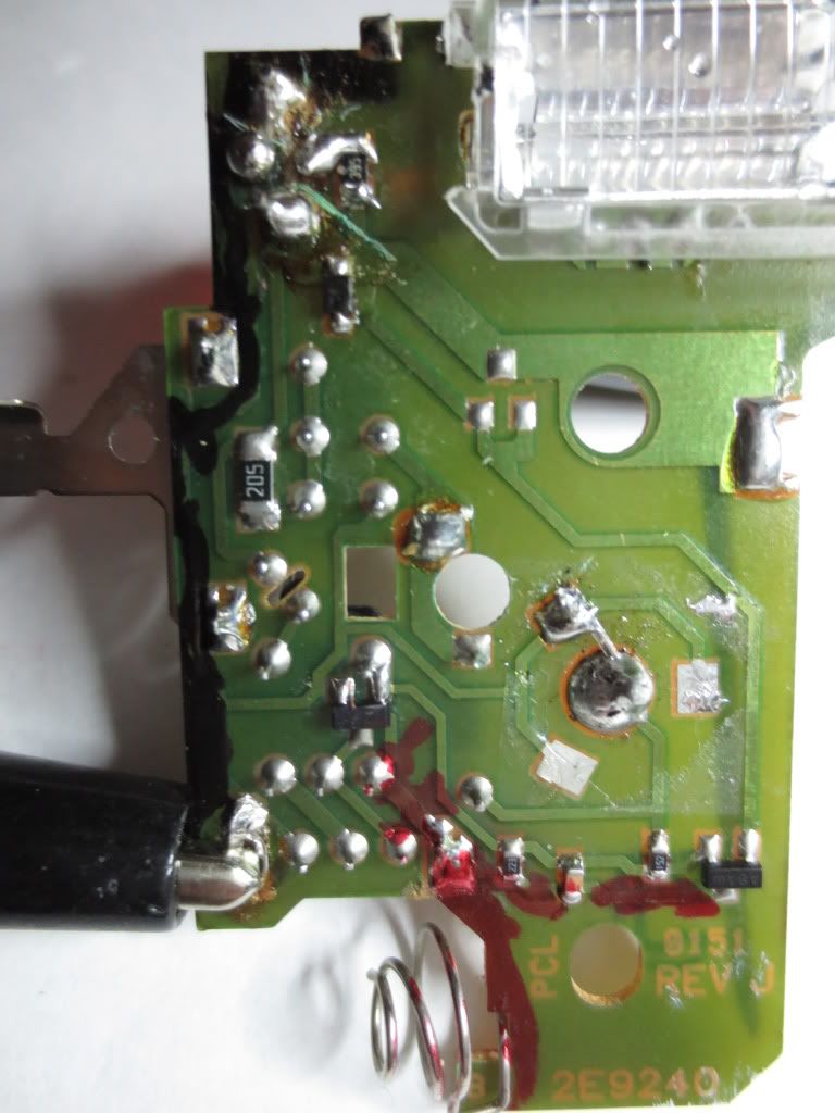
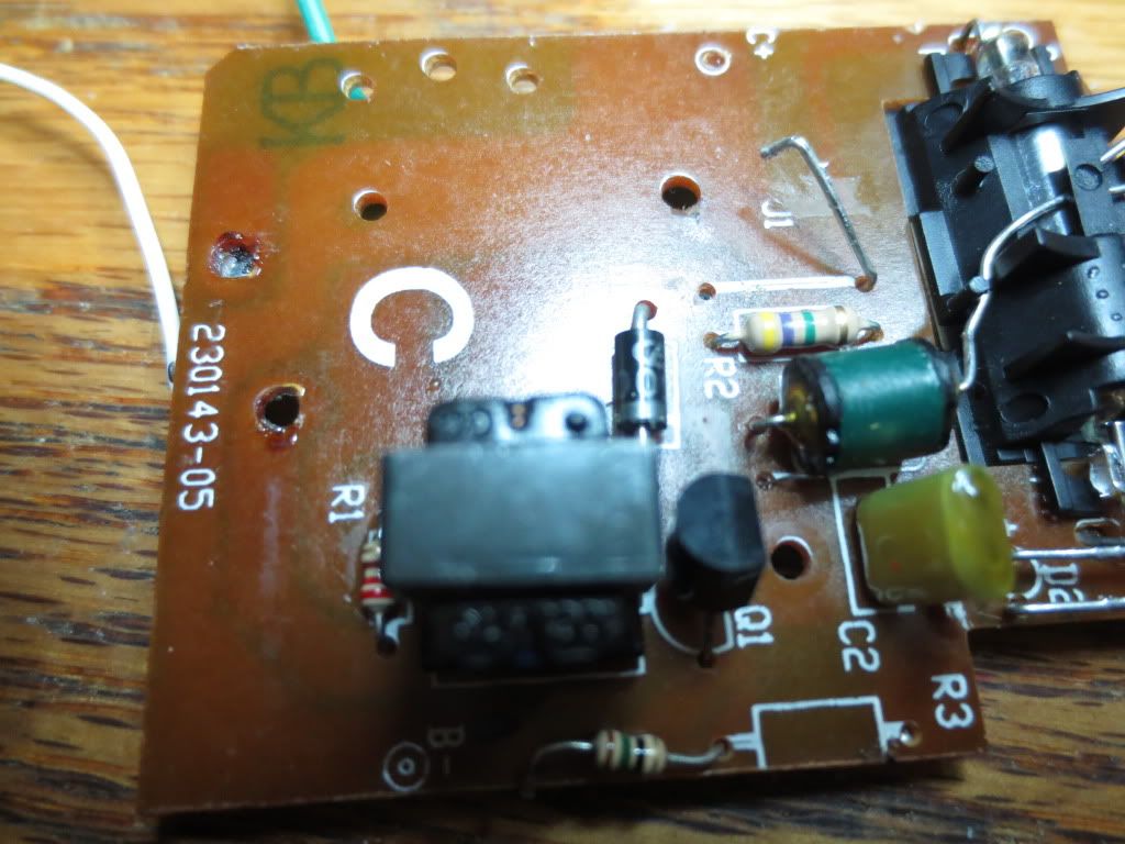
Here is the circuit board after the large flash capacitor was removed to prevent getting shocked while the board is off:
The second thing to do is to mark the battery plus and common circuit traces to all components as far as you can.
Once the trace reaches a component, stop marking. That gives you an idea of where you can connect the
battery later. It may also show you the general area of board you will need if you intend to put the circuit into the
base of the CFL bulb. Note how the charging pushbutton is jumpered with a discarded resistor tail I had.
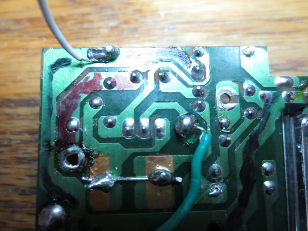
After comparing the top and the circuit traces, I soon realized that everything to the right of the transistor was
not needed. To test that theory, I removed the jumper at the top going to the other components and the LED.
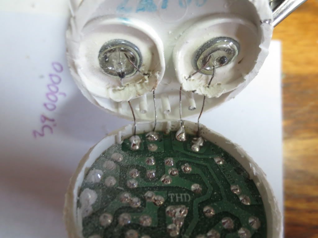
I hooked one CFL filament to common and connected the battery with jumpers. Then I CAREFULLY jumpered the
other CFL filament to each side of the diode to see if it would light. The bulb lit up on the cathode side!
BE CAREFUL! The 200 volts can shock you enough to get hurt by objects nearby when you react!
I later resoldered the red LED back onto the resistor at the bottom and hooked the + anode to common like it was.
It is a good idea to keep any voltage warning indicators if you can!
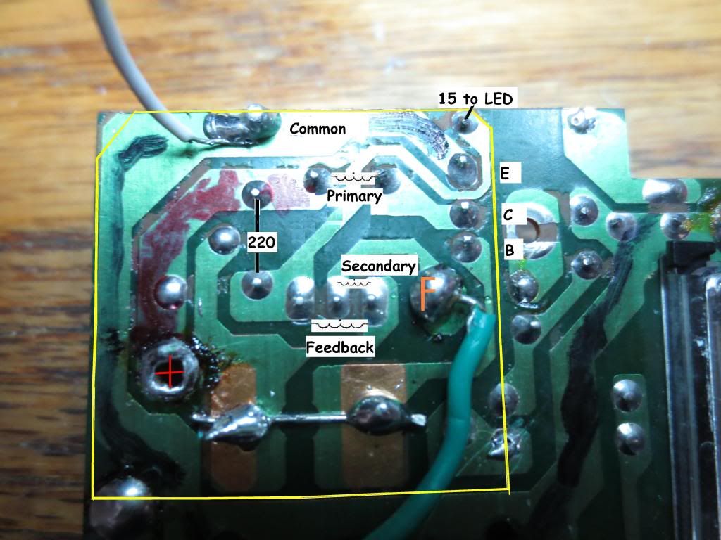
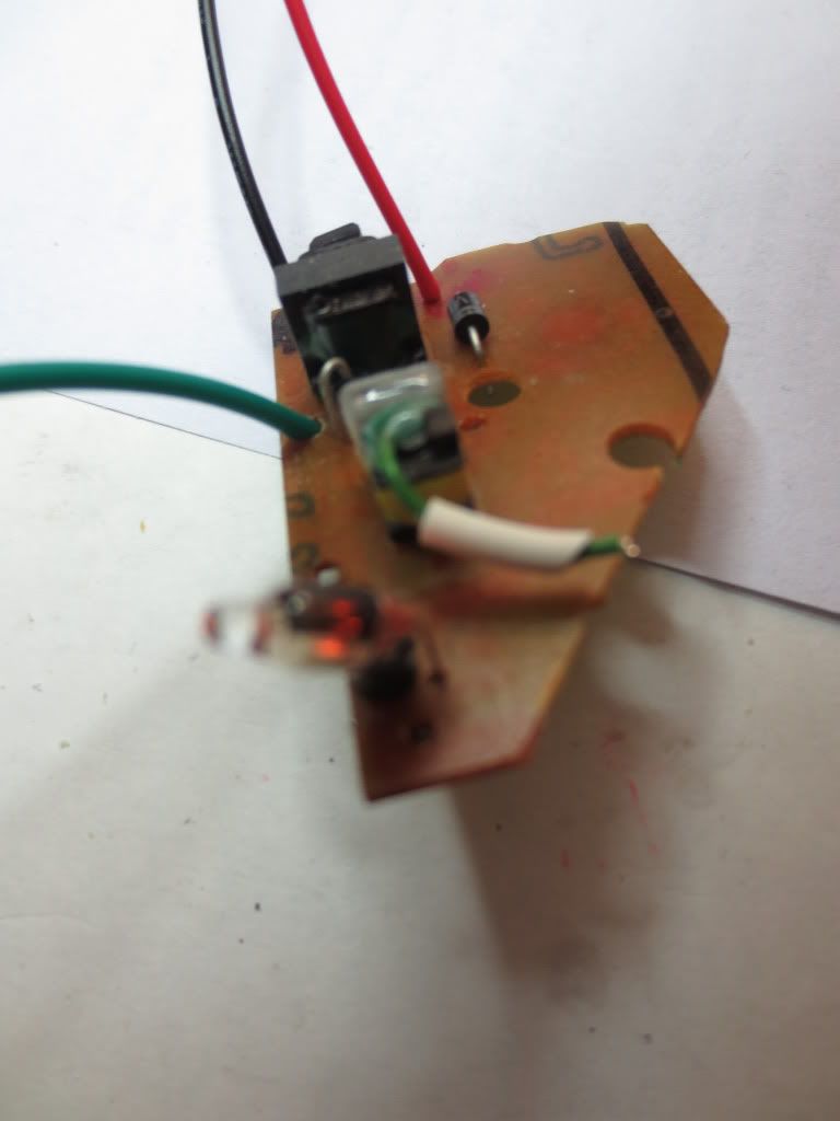
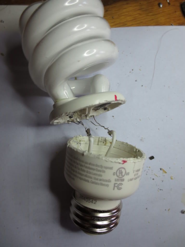
This is the final area I chose to keep. The battery + and hot filament F and Common are noted:
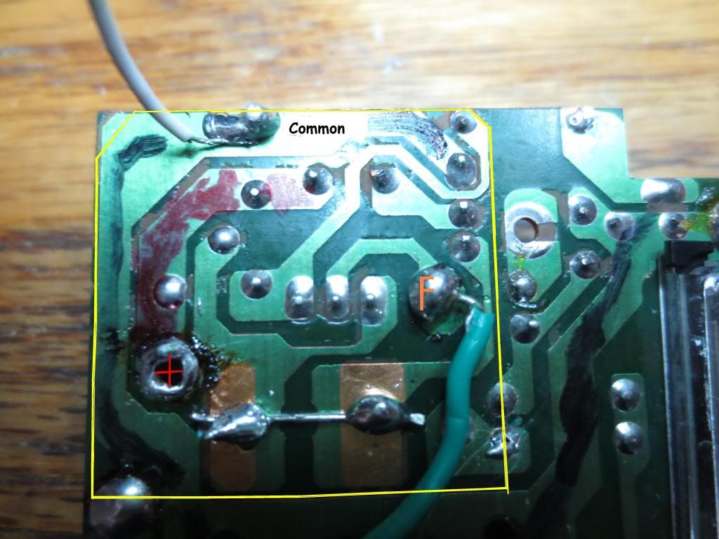
I decided to later drill a hole for the common lead to the socket base on the left side. I soldered the board into the
base socket top down before connecting the filament hot wire and common to the board. I used clay as insulation
between the filament and circuit board bottom. A short would be more likely on that side so insulate it somehow.
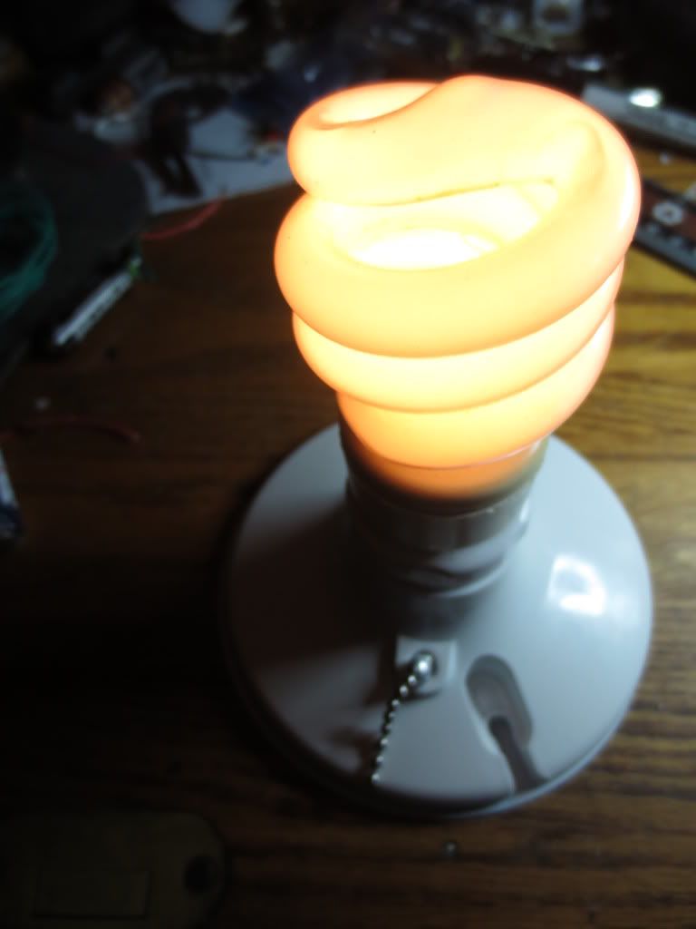
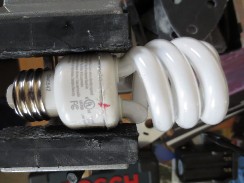
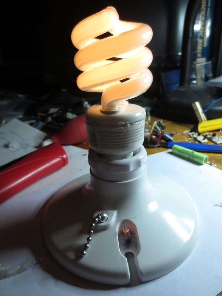
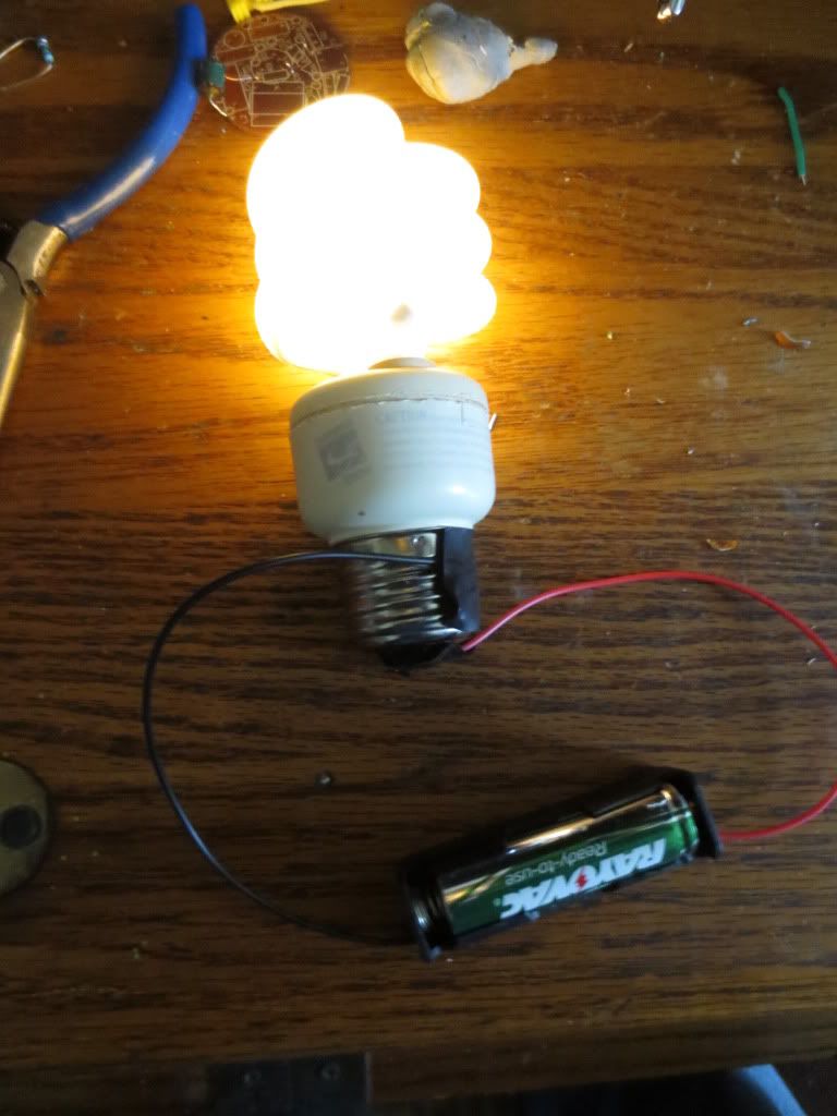
Here is the final test I did using tape to hold the wires on the 2 base socket connections. Naturally, plus is on the center:
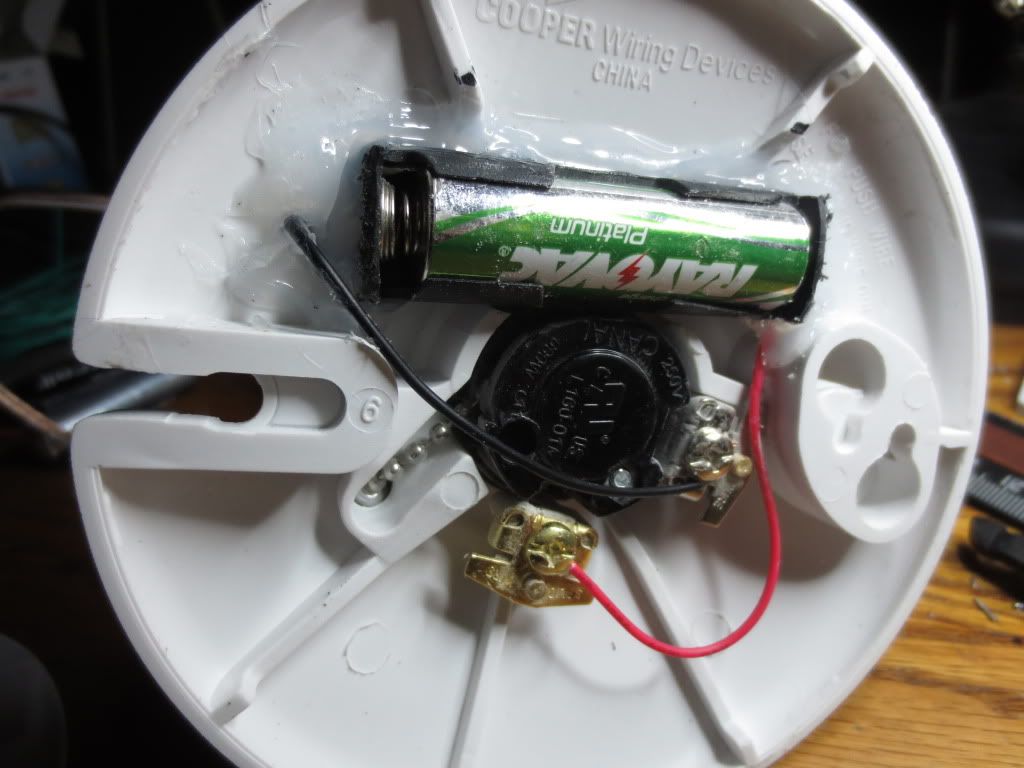
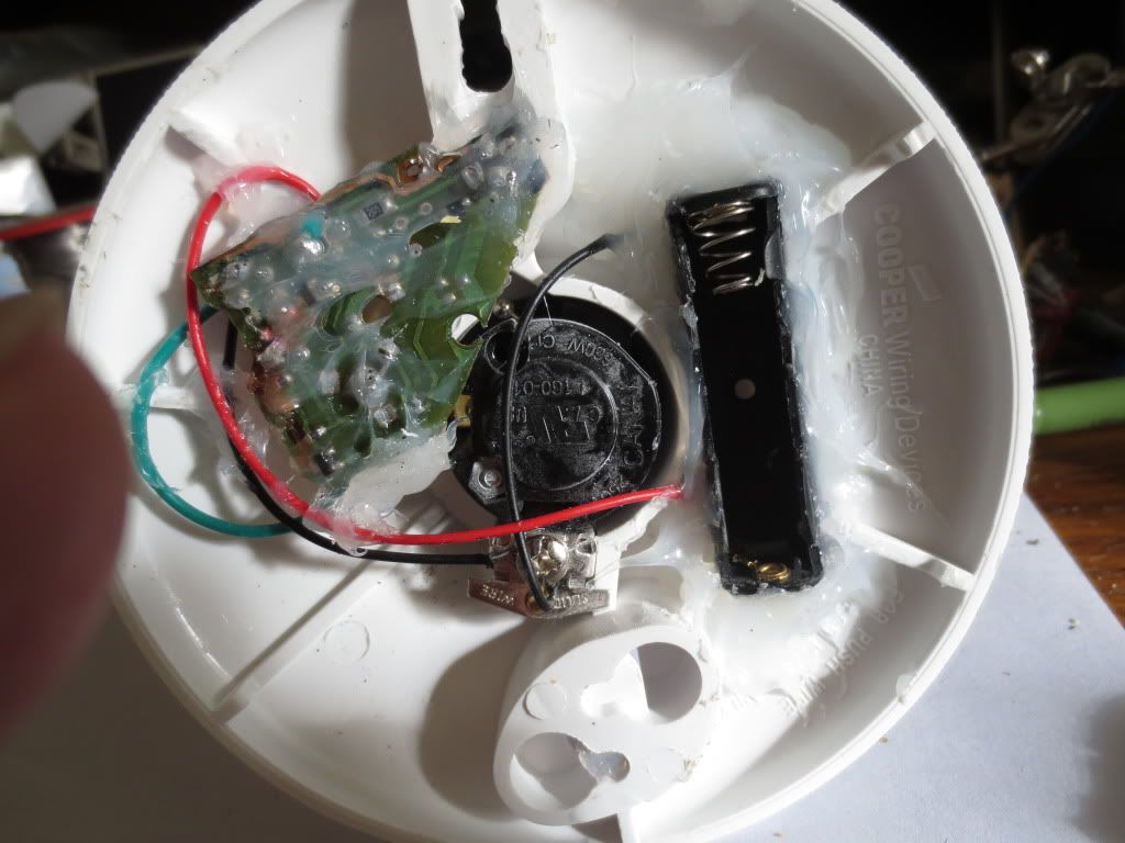
The next step is to find an appropriate mounting base for the bulb. A nice piece of wood, an old style pull string socket
and a battery holder, hidden or not should do it!
I was also thinking about making a bulb with a small button battery and a tact switch in the thread base so I
could just hold the bulb up and press the switch to light it up like magic. Switch could also work when screwed
into a socket too. Just make sure it is not 110 volts!
Mark the base if it might fall into the wrong hands!
It draws about 230 ma with one AA battery. Two batteries in series may blow it up!
The circular board up top is the old CFL circuit board minus the components. I used it as a template for the new board.
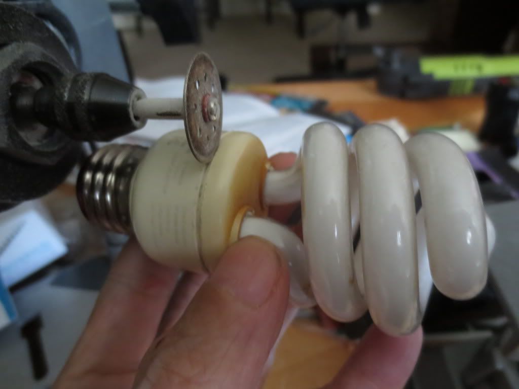
I cleaned up the pry marks with a Sonicrafter vibrating tool sanding pad using the paper off the side of the pad to
get into the slim area. Those vibrating tools are amazing, but very loud. I also used it to cut the PC board clean.
PS: I sold five 5252F LED drivers on Ebay today. My first Ebay sale! Maybe I'll start selling magic light bulbs?
http://www.ebay.com/itm/Five-5252F-one- ... 1e87a11eaa
PSS: Wonder it this would work with those Edison bulbs too? They'd be real hard to take apart...