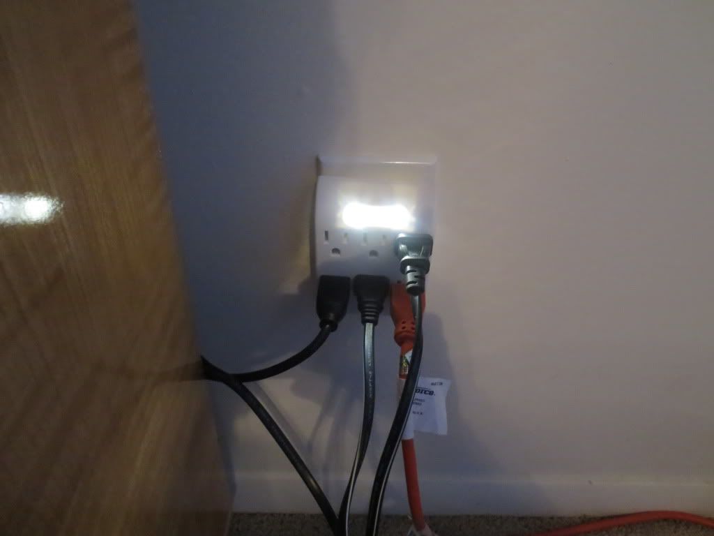
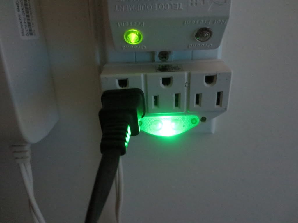
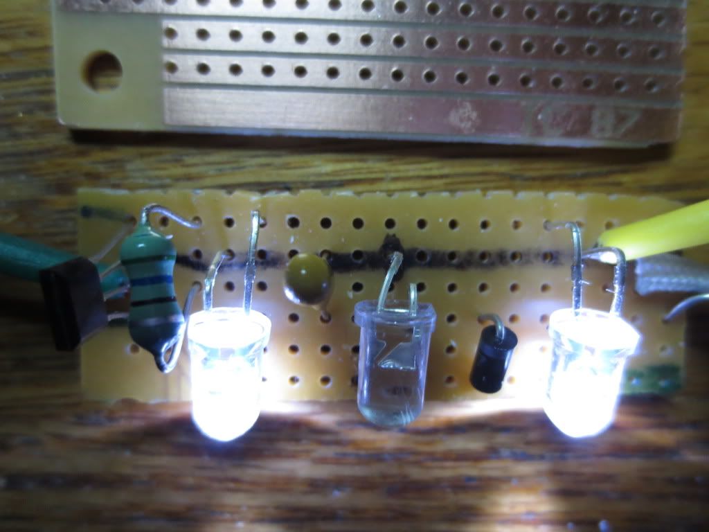
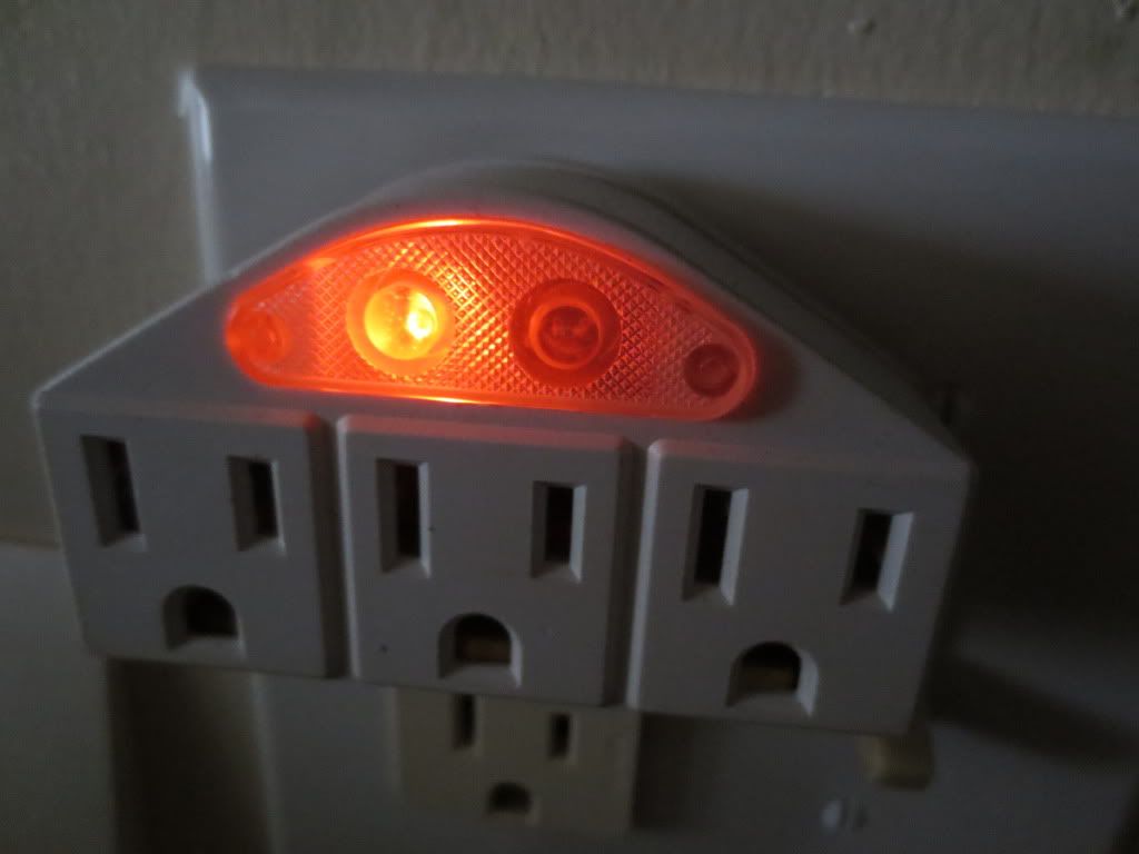
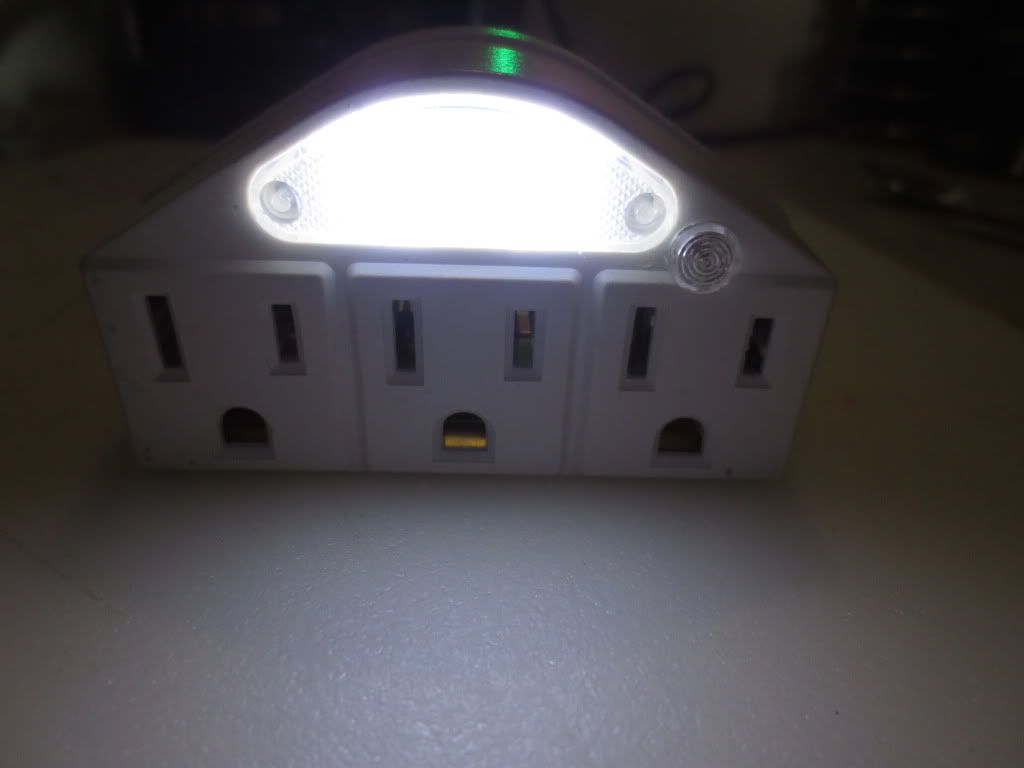
I finally tested that ugly orange night light LED in circuit without blowing it up:
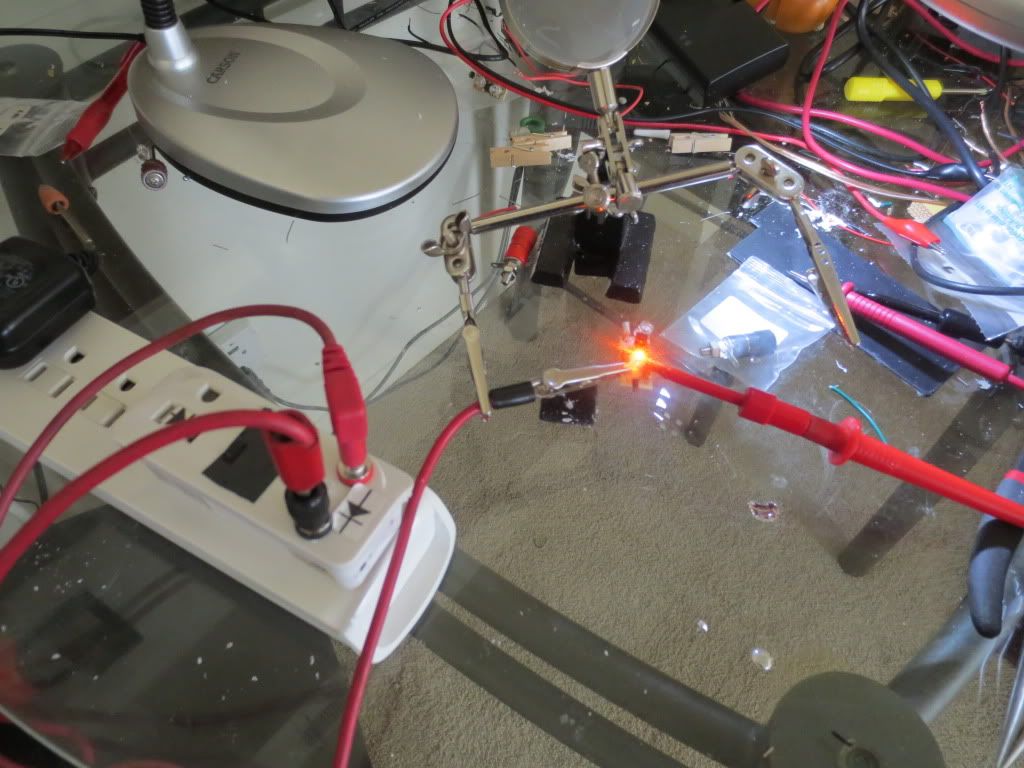
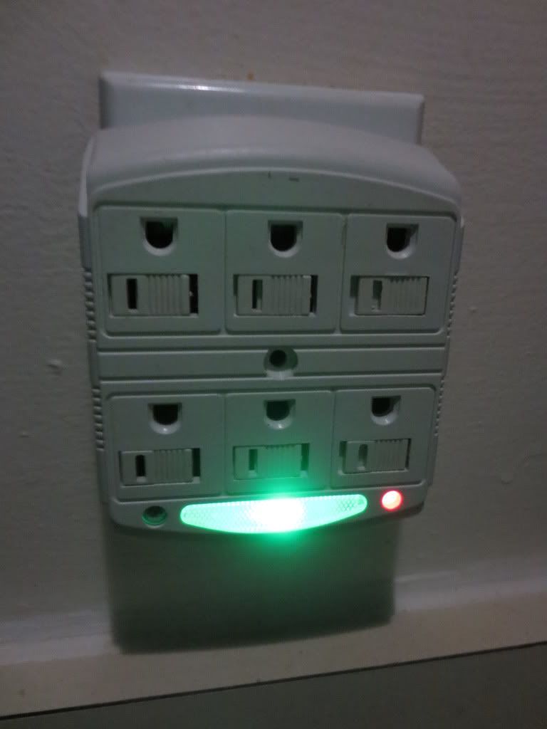
It is pathetically not bright either, but it killed the green power LED on the tester while it was connected.
The power indicating LED is in parallel with the tested LED, so that may happen when the test LED uses
less voltage. The green LED is a bright one rated at 3 volts.
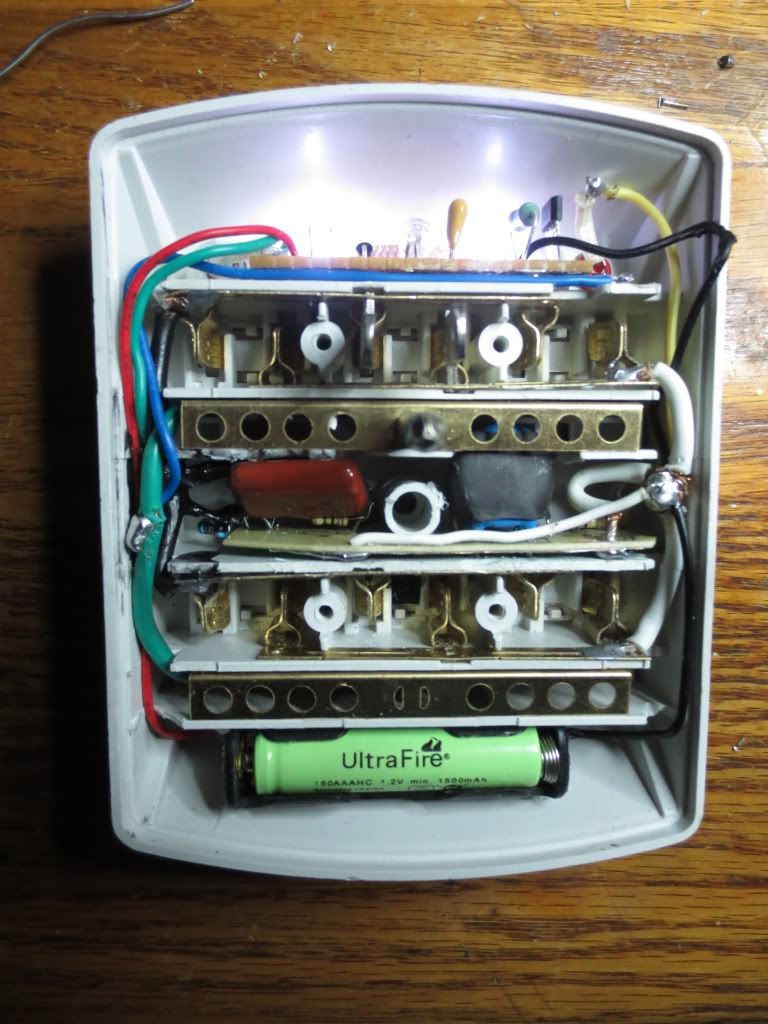
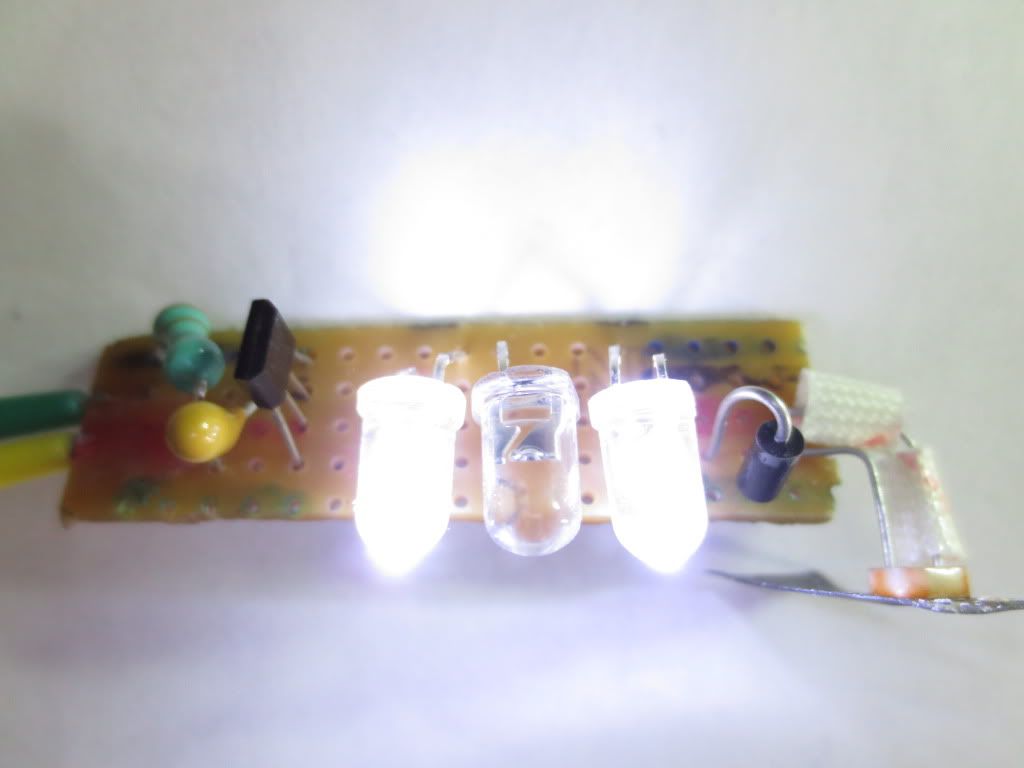
The LED tester I came up with works off of capacitive reactance and automatically limits the LED current
to 20 milliamps using 120 volts at 60 cycles per second:
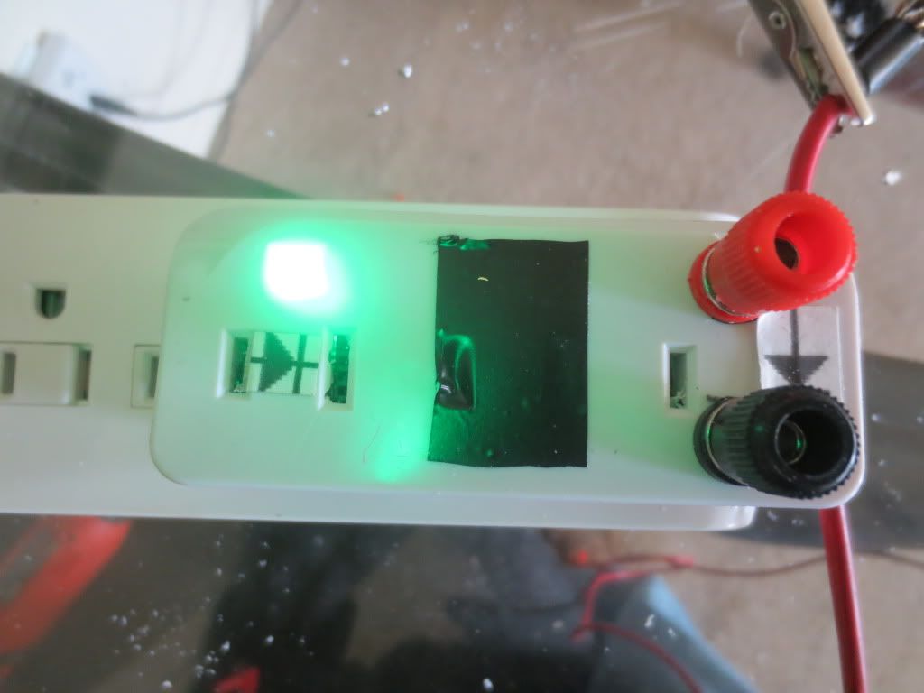
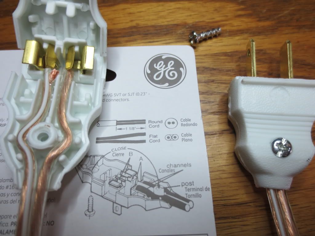
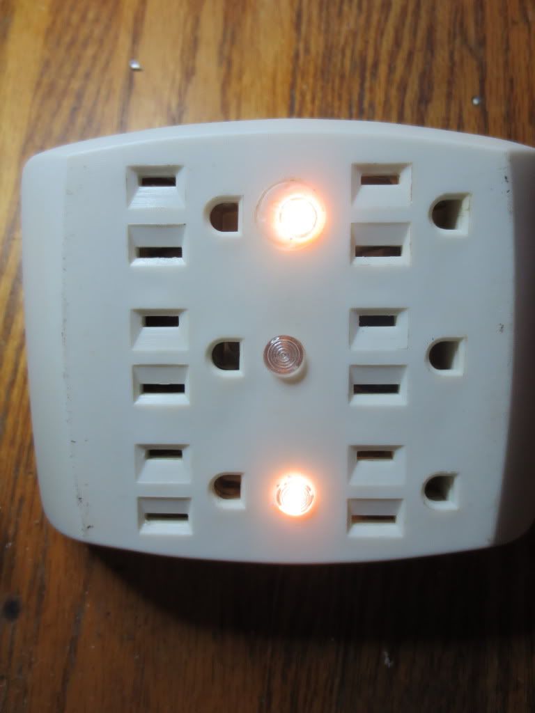
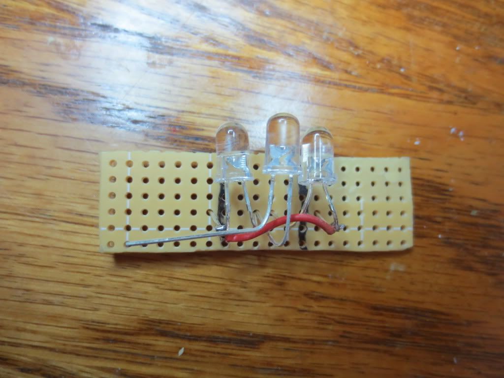
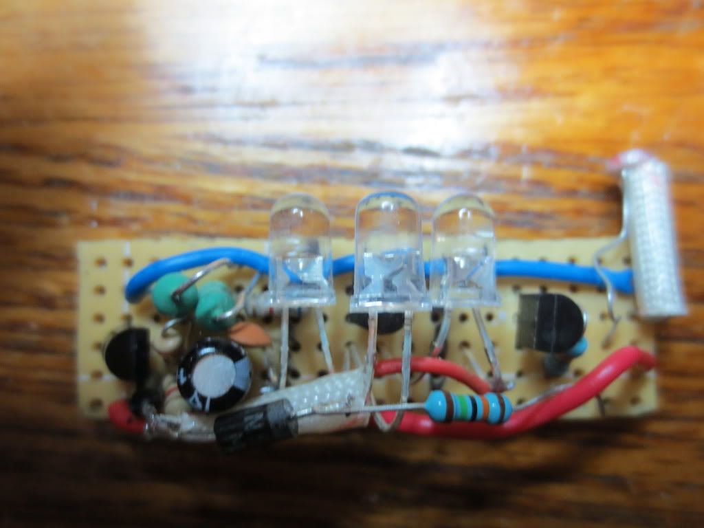
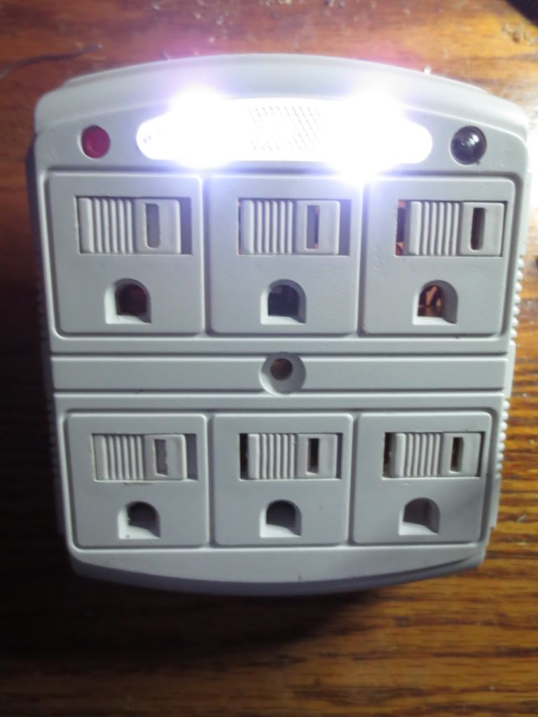
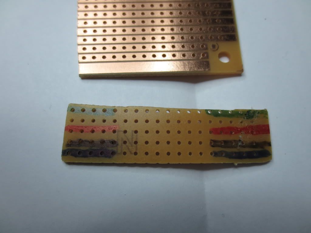
I had a 3 outlet multiplier box so I built the circuit inside of it. It has two rows of female pin connectors in the slots where
the AC used to be to test and compare brightness of a few LED's at once.
Here is some QB code to calculate the current available with different AC voltages and high voltage capacitors:
Code: Select all
'Inductive Reactance = 2*pi*frequency*inductance
'Capacitive Reactance = 1/(2*pi*frequency*capacitance)

DO
  INPUT "Enter AC supply voltage: ", voltage& '= 120
LOOP UNTIL voltage& > 0

ACfreq = 60 ' 50 'in Europe and Asia?
DO
  INPUT "Capacitor farads(1uf = .000001) or microfarads >= .001:"; capacity '= .000000068
LOOP UNTIL capacity > 0

IF capacity >= .001 THEN capacity = capacity / 1000000

PRINT USING "Capacity = .############ farads"; capacity

Creact& = 1 / (8 * ATN(1) * ACfreq * capacity)

PRINT USING "Reactance = ########,.## ohms"; Creact&

current = voltage& / Creact&

PRINT USING "Supply Current = ##.###### amps"; current
Note that the calculation uses 60 Hz for American electric supplies. Europe and Asia use 50.
The capacitor value can be entered in Farad decimal point values or Micro Farads greater than .001.
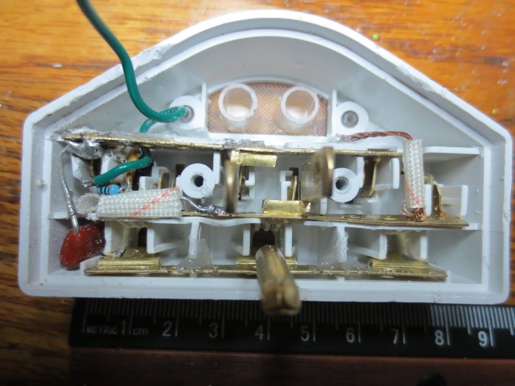
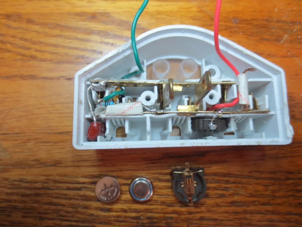
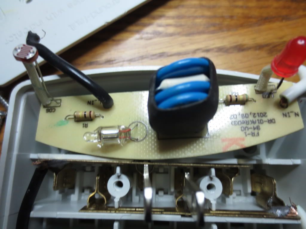
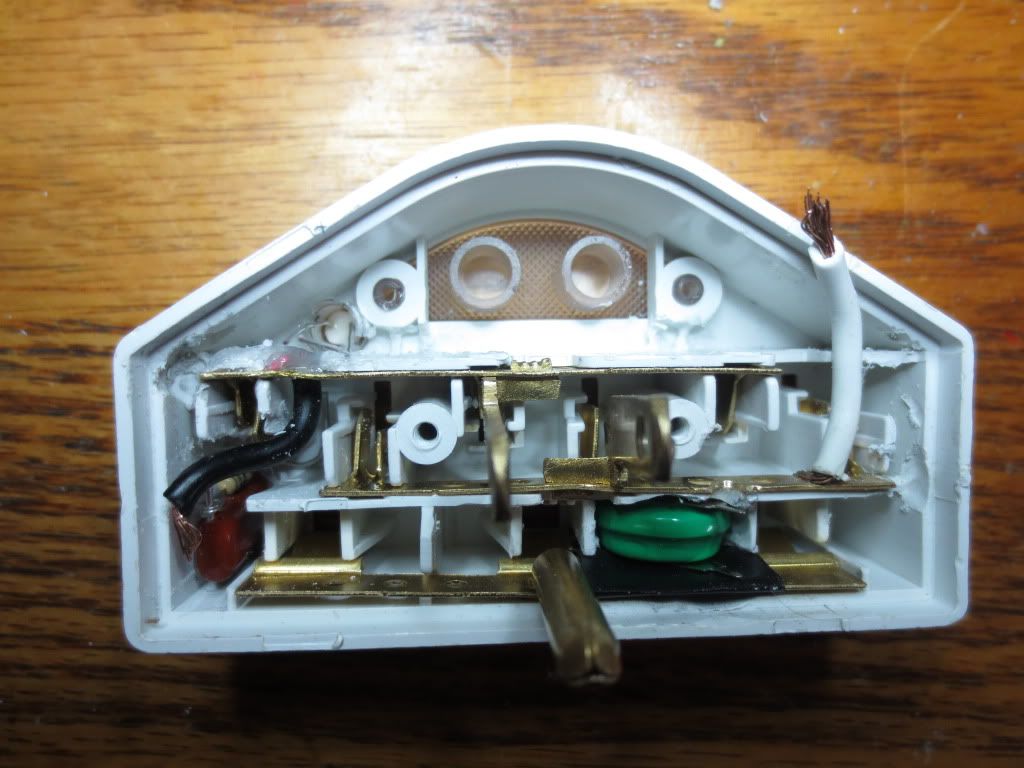
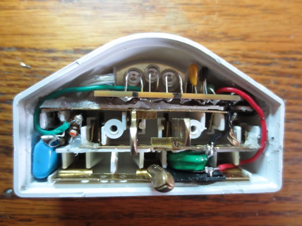
The circuit I used, at top left, uses a .47 uf, 250 volt capacitor and 1K resistor to limit current:
I added a resettable fuse rated at 1.35 amps and a MOV both rated at 30 volts.
The narrower slot (top bus pictured below) should be the bus that the capacitor is soldered to.
To prevent reverse polarity problems connect the 1K resistor to the ground prong instead of the common bus!
If the tester does not have a proper ground it will not work. Safety first when working with high vltages!
I also added BNC connectors for testing LED's in circuit or for volt meter readings when needed.
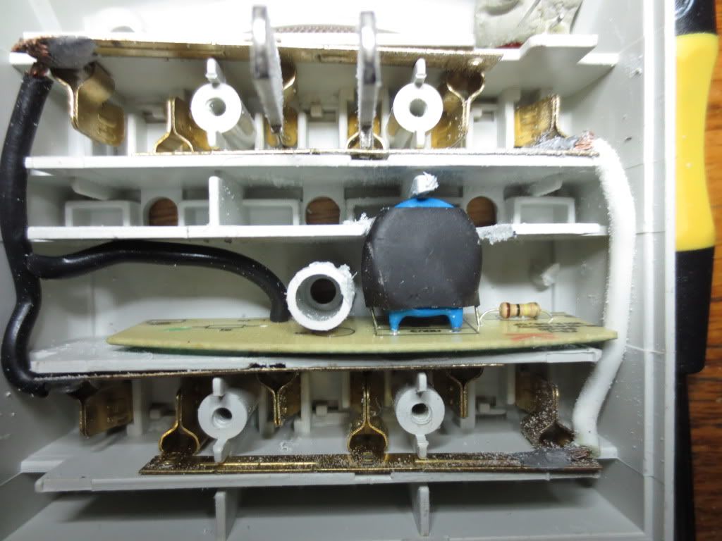
Note: The capacitor must be rated for at least 200 volts! Also put a 1 Mega ohm resistor across it
to drain any left over voltage when disconnected.
Also, do not remove the round ground prong! It keeps the high voltage line in the right place on the capacitor!
That way the high voltage is best isolated from the user. Again, don't plug the circuit in with the back off of it!
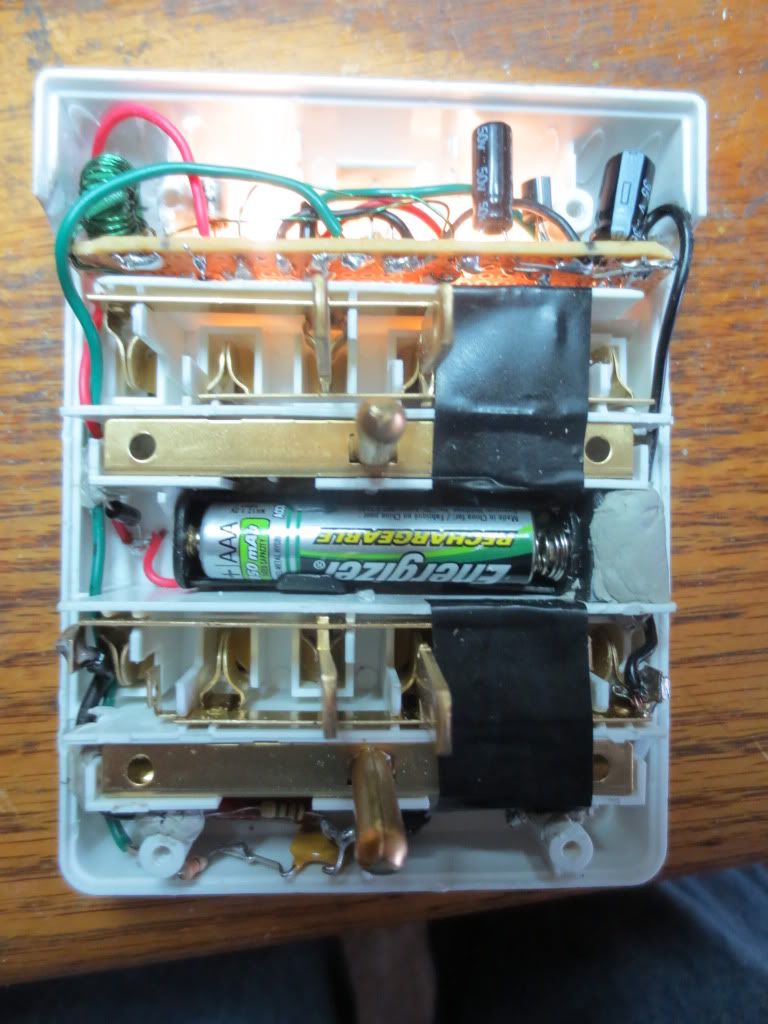
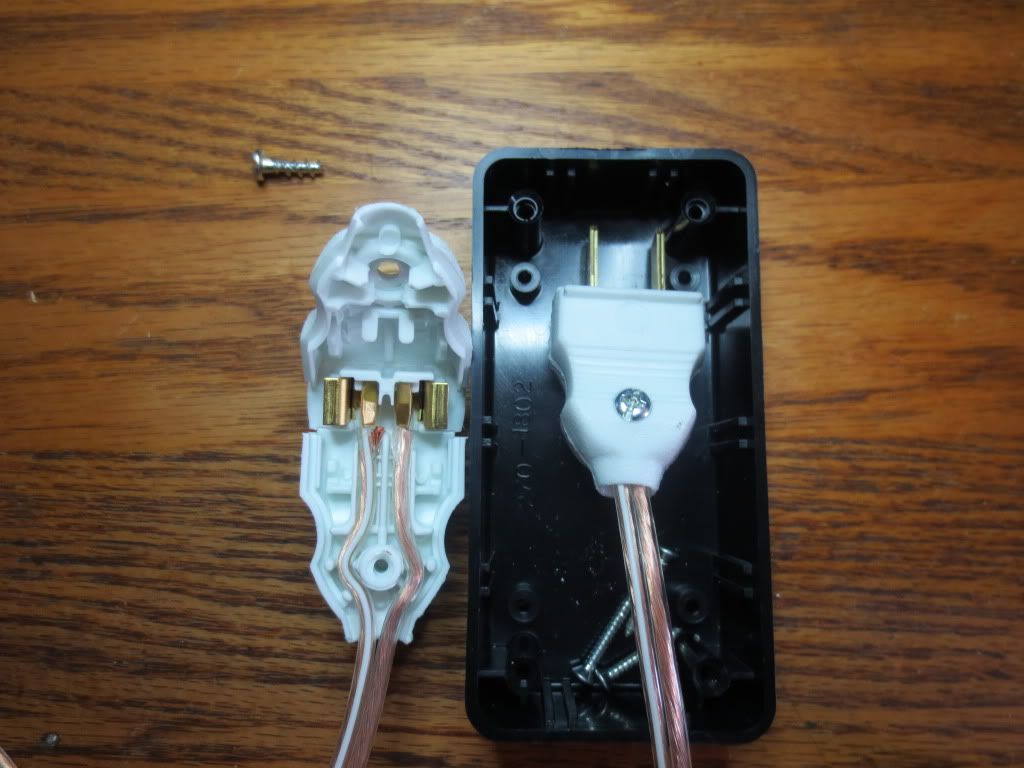
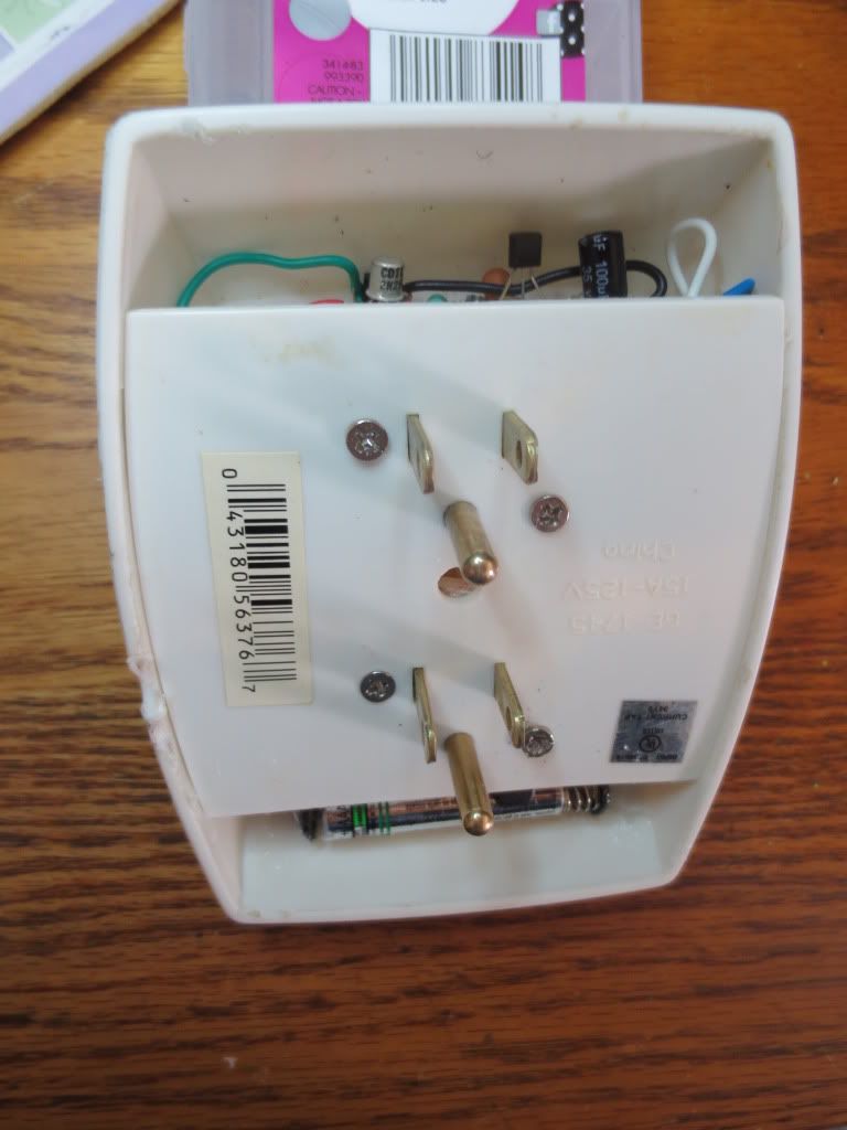
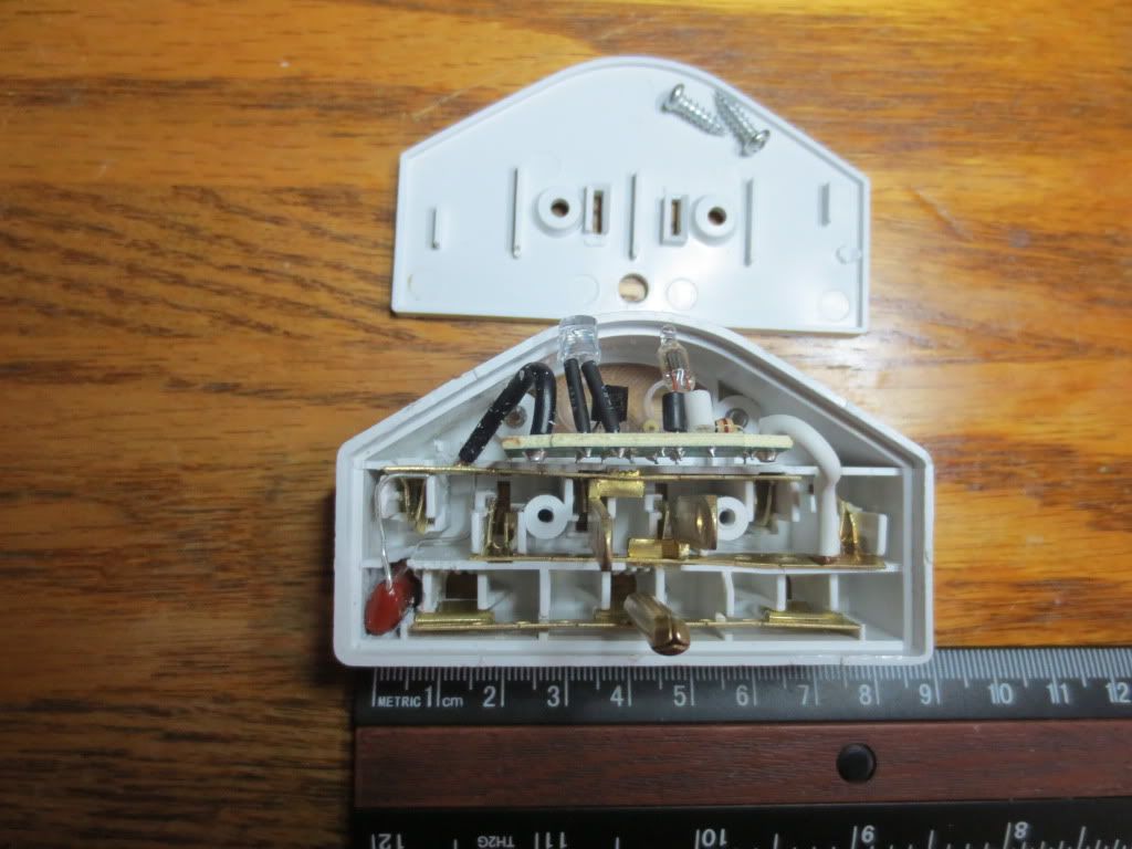
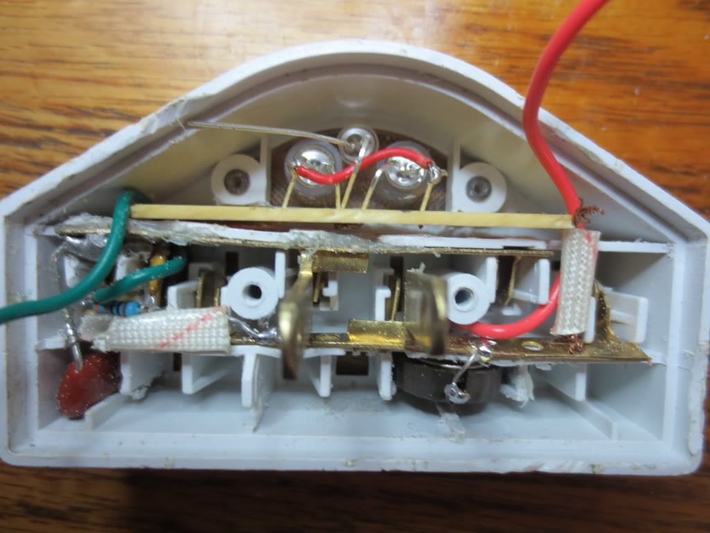
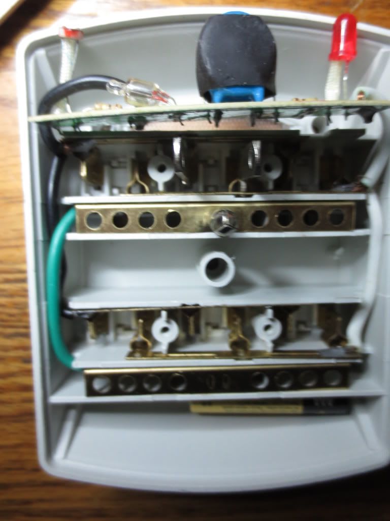
This is the box I made it out of. The buses can be broken off by bending them back and forth with pliers:
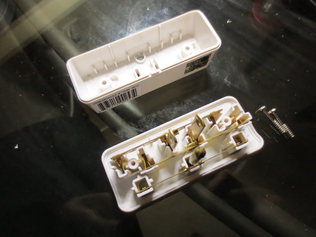
I broke off the buses to the other 2 outlets so that only the center one would have power. To prevent accidents,
I taped over that center outlet too. I kept enough of the line buses to keep them stable or they might wobble too much.
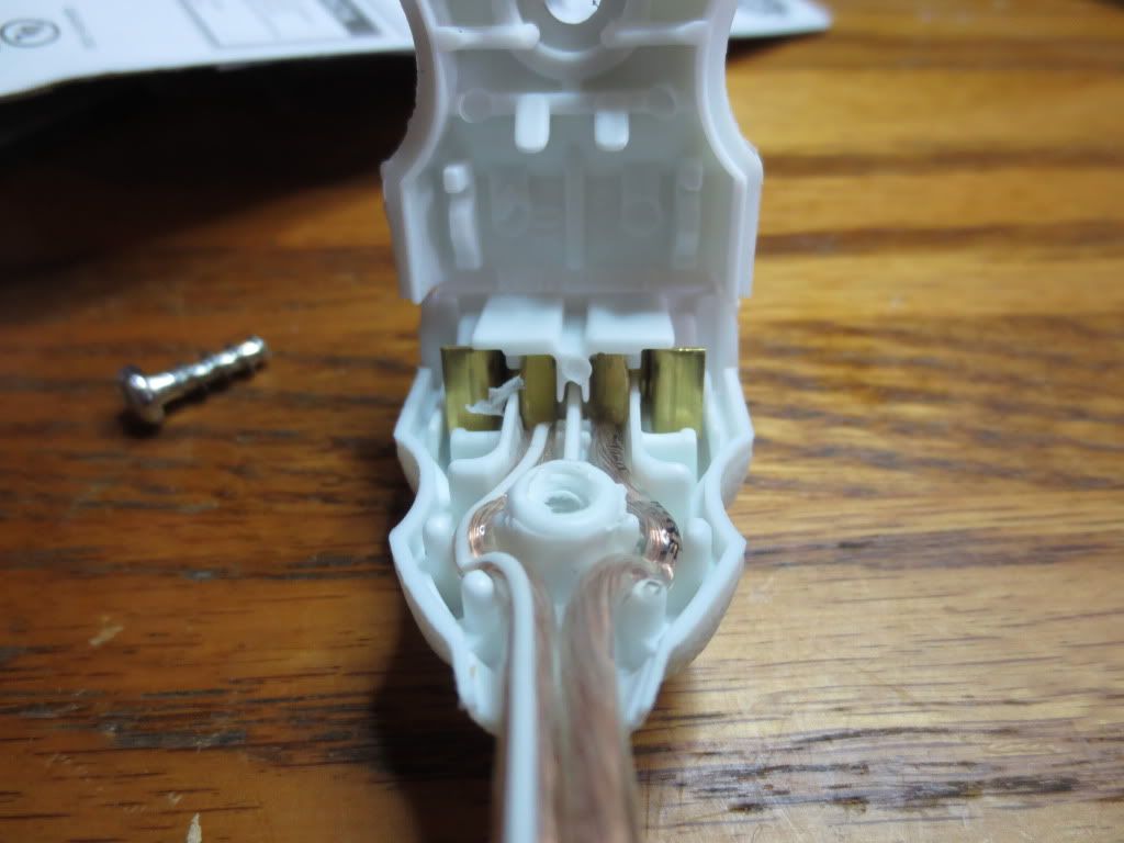
The 5mm green LED slid right into the ground hole and rows of female pin header connector strips fit tightly in each prong slot.
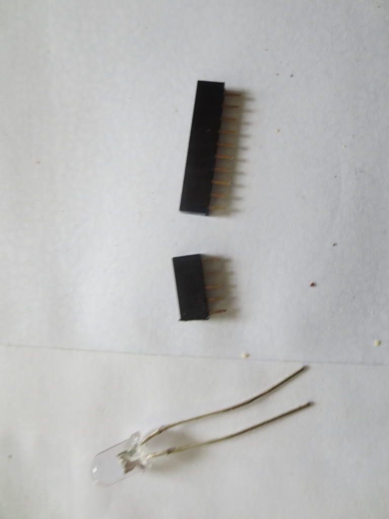
After I cut the strips to fit each slot. I soldered a resistor wire to every connector so the pins would not fall out.
They will all be the same polarity anyhow. One slot took 4 and the other took 5 to fit tightly.
Since the green LED is in parallel with a tested LED, it may turn off if the voltage drop across the test
LED is less than 2 volts.
Use a bright 3 volt or higher LED for the power indicator or other LED's may not light!
The biggest headache was the BNC connectors as the back of the box is tapered in. Took a lot of effort to fit.